This thread has been locked.

If you have a related question, please click the "Ask a related question" button in the top right corner. The newly created question will be automatically linked to this question.

TPL8002-25: Tap Digital Potentiometer Operation

Part Number: TPL8002-25

Tool/software:

Hello,

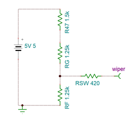
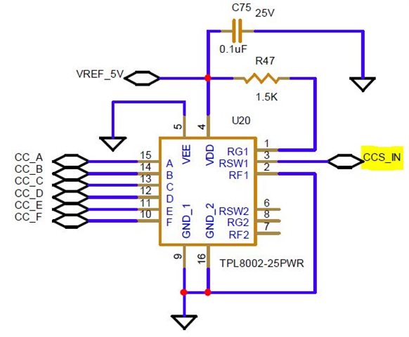
I have read your switch truth table from the data sheet and just need some additional clarification. I was given a circuit using your device that I need to evaluate, but want to make sure what resistance to expect at the RSW1/2 outputs as the circuit I am evaluating uses the RSW1 output and connects to a non-inverting input of an external differential amplifier while the inverting input connects to gnd (opposite of the data sheet description). The external amplifier will ultimately produce a 100uA constant current source. I understand the wiper has a constant resistance of 420 ohms, with a setting of 32 (b100000) will the RG and RF terminals cancel (0 dB attenuation) and only the 420 ohms of resistance is observed at RSW1? Circuit configuration shown below, maybe a couple of additional setting examples would help.

Thanks,

Kevin

  • Hi Kevin,

    I am not sure I fully understand what you mean.  Under no configuration, will any resistance be "Cancelled".  Could you share your circuit configuration as a figure/schematic? Assuming the POT is set to mid-scale code, my understanding is that you would have a three-leg resistor network, with an additional 1.5kΩ on the RG side.  

    Thanks,
    Paul

  • Hi Paul,

    Thanks for the quick response. I may have misunderstood the data sheet. Anyhow, the circuit was provided in the initial Forum write up and is displayed again below for your reference. I also included the amplifier circuit where the RSW1 output eventually connects to, just for clarity if this helps. Since there is no cancelation and to lessen my confusion, I think just knowing what the device outputs at a specified setting is sufficient; e.g. Decimal Control = 40, RSW1 = 6dB, which equates to 2V. So it may not be necessary to know the actual resistance at RSW1. Do you agree?

    I also need to confirm another item. The recommended operating voltage range is 2.5-4V and the circuit below shows VREF_5V, which is actually 3V, applied to VDD. Since VDD is powered by 3V, is it acceptable to tie the appropriate Decimal Control bits to VDD to achieve a high or logic 1?

    Thanks again,

    Kevin

  • Hi Kevin,

    IN this case, you have the TPL configured as a simple resistive divider going into a high-impedance node.  So it should work fine in this case and the absolute resistance is not as critical.  That beind said, you have a series 1.5kΩ resistance to bias the divider.  That is not a probably, but keep in mind that the absolute resistance of the TPL could be ±20%.  The ratios though are very linear.

    Using 3V for the logic inputs is fine in this configuration.

    Thanks

    Paul

  • Hi Paul,

    Appreciate your inputs. I believe I have enough info to carry on.

    Thanks again and best regards,

    Kevin