- Ask a related questionWhat is a related question?A related question is a question created from another question. When the related question is created, it will be automatically linked to the original question.
Tool/software:
I am putting ADS8694 in one of my design.
The input is bipolar from -2V to 2V. and i am using the internal reference 4.096V with input range setting 0.625 x 4.096= +/-2.54V.
out of 18 bit data output 16 bit are changes as per input changes. but the 2 bits remains unchanged as input varies.
I am not getting why these two bits remains unchanged.
Please suggest the solution.
As per the last discussion,
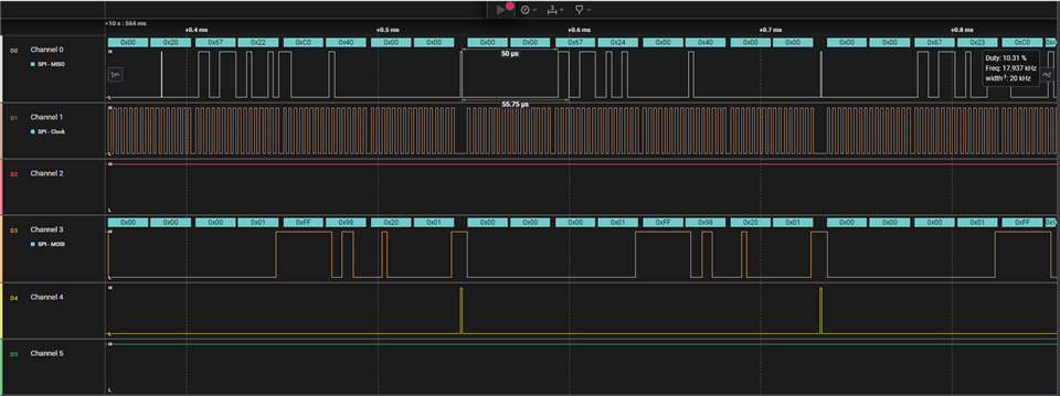
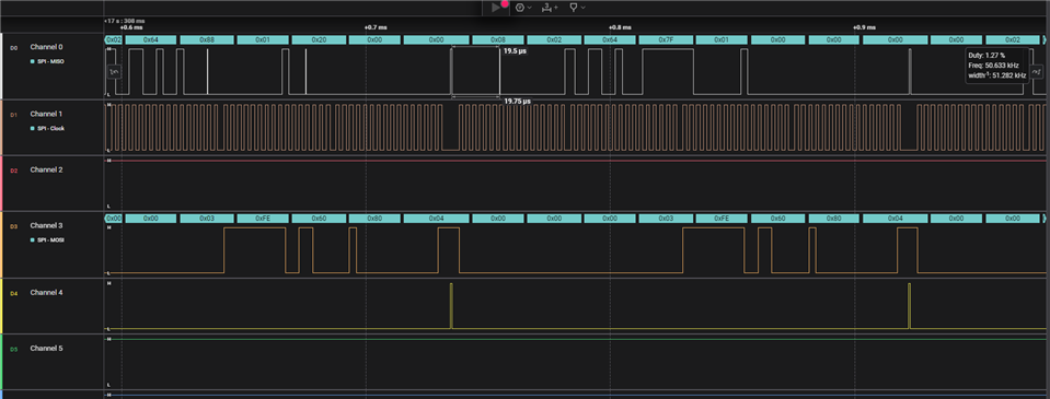
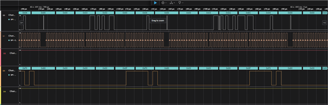
I am attached here, the schematic and the logic analyzer plot for the 2.255mV and 1500mV input for your reference.
In the logic analyzer data channel 0 is SDO, Channel 1 is SCLK, Channel 3 is SDI.
Please let me know which 18 bits should I consider as data.