Other Parts Discussed in Thread: OPA2828
Tool/software:
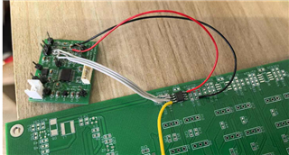
This is a test board we made based on the TI DAC8811 development board, where C2, C3, and R5 were not soldered
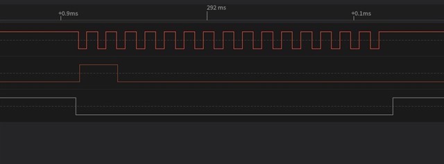
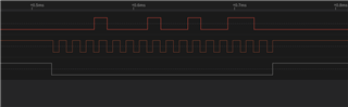
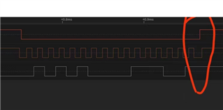
This is the timing sequence of CLK, SDI, CS
for(i=0;i<36;i++)
{
// dD = -0.5;
dD = sin(i*2*3.1415927/36);
usDat = (dD+1.0)*65535/2 ;
DA_Set_Fun(usDat);
Delay_2us(10);
}
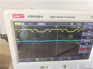
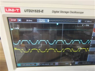
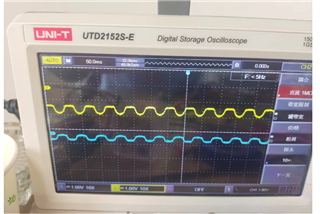
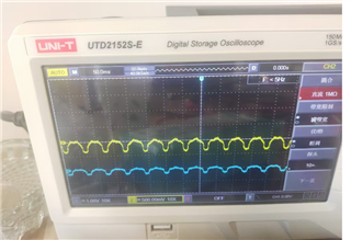
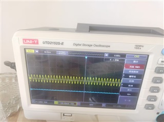
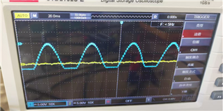
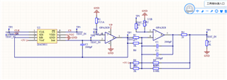
This is a sine wave output
But the signal is wrong. The following figure shows the data of TP8 and TP7, with yellow indicating TP8 and blue indicating TP7