Tool/software:
Hello,
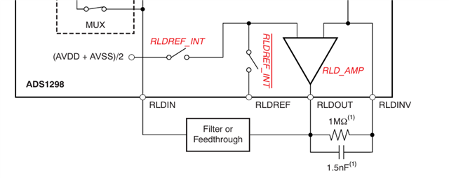
The manual for ADS129xLow-Power,8-Channel,24-BitAnalogFront-EndforBiopotentialMeasurements includes sample code for RLD Measurement/Setup in section 10.1.1.2 Right Leg Drive.
The code is as follows:
WREG RLD_SENSP 0x07 // Select channel 1-3 P-side for RLD sensing
WREG RLD_SENSN 0x07 // Select channel 1-3 N-side for RLD sensing
WREG CONFIG3 b’x1xx 1100 // Turn on RLD amplifier, set internal RLDREF voltage
The CONFIG3 setting in the third line is confusing, as it has bit 1 set to 0. Bit 1 is "RLD_LOFF_SENS", a setting that enables RLD sense (1) or disables it (0). The example code has it disabled. Would that not mean we would get no RLD functionality? Or am I misunderstanding this bit.
As a separate question. CONFIG3 has another setting, "RLD_MEAS" on bit 4 decides whether RLD is on any channel or set to specific ones ("1 = RLD_IN signal is routed to the channel that has the MUX_Setting 010 (VREF)"). If we set Ch2 to be the one that receives RLD_IN signal in the CHnSET register, but have In1P and In1N as the only positive and negative leads connected to the body, would all future registers (ie the Positive/negative RLD Signal Derivation Registers and LOFF sense registers) have to point to ch1 or ch2?
Thank you


