Tool/software:
Hello,
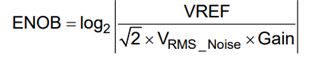
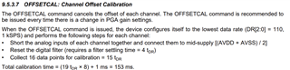
After sending the calibration command, I put the ADS in short-circuit mode and performed some acquisitions to check the calibration. The measured values are not very close to 0. Normally, the ENOB for my configuration is 19 bits, which should give error values of up to 32, but the values I'm getting are much higher.
Before calibration :
CH1 = -1137
CH2 = -989
CH3 = -1075
CH4 = -993
CH5 = -901
CH6 = -832
CH7 = -898
CH8 = -954
After calibration :
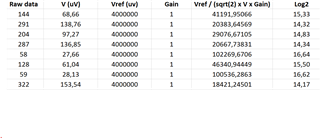
CH1 = 144
CH2 = 291
CH3 = 204
CH4 = 287
CH5 = 58
CH6 = 128
CH7 = 59
CH8 = 322
The results improve after calibration, but do not conform to the 19-bit ENOB. What's more, the results are stable, indicating that the problem is not noise-related.
Do you have any idea of the cause of this problem?