This thread has been locked.

If you have a related question, please click the "Ask a related question" button in the top right corner. The newly created question will be automatically linked to this question.

ADS124S08: Schematic review

Part Number: ADS124S08
Other Parts Discussed in Thread: TL431

Tool/software:
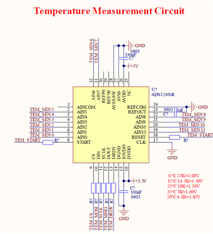
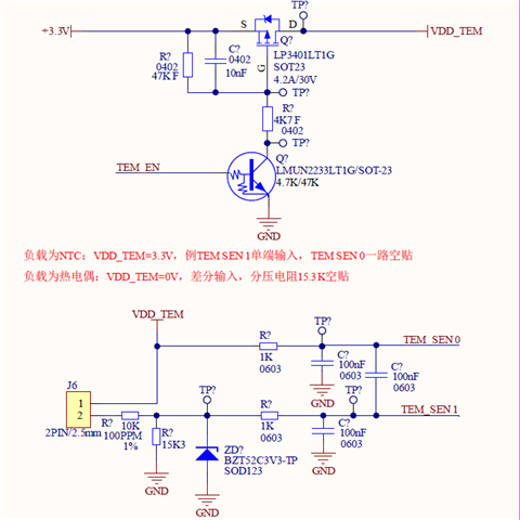
Can this design be compatible with NTC and thermocouple sampling?

If load is NTC, VDD_TEM=3.3V, TEM SEN1 single ended input, TEM SEN0 is grounded.

If load is thermocouple, VDD_TEM=0V, differential input, 15.3k resistor will be not mounded.

  • Hi Fabio Gou,

    Please respond to my comment in the Thread Tracking Toolkit?

    -Bryan

  • Could you provide some guidance for the  NTC and thermocouple sampling?

    My customer and me are not so familiar with our ADC. 

  • Hi Fabio Gou,

    Thanks for providing the requested information

    Some comments / questions for you:

    • I would recommend a pull-up to IOVDD / DVDD on the RESET pin, to ensure the ADC powers up in a known state
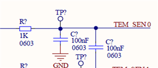
    • I would reduce the size of the capacitors on the ADC inputs. They are all 100nF right now, maybe 10nF or 4.7nF would be better. Also the common-mode caps (the caps to ground) should be 10x smaller compared to the differential capacitor between the inputs. So if the differential capacitor is 4.7nF, the common-mode capacitors should be 0.47nF
    • Why is TEM SEN0 (AIN0) grounded for the NTC?
    • What is the purpose of the 10k resistor right next to J6?

    -Bryan

  • Hi Bryan,

    Thanks for your feedback.

    The J6 is connecting to NTC or  thermocouple.

    When NTC, this part will not be mounted. TEM SEN1 is connected to ADC to measure the voltage.

    (Three resistors to divide the voltage. It seems the 10k resistor is not necessary, right? )

    When thermocouple, 15K3 will bot be mounted.

    In this situation, whether the 10k resistor also is not needed? 

    By the way, now the 3.3V (for NTC) is provided by LDO. But the accuracy is nearly 1%.

    Whether using 0.5% accuracy TL431 will be helpful to improve the accuracy? 

  • Hi Fabio Gou,

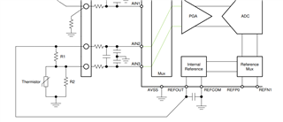
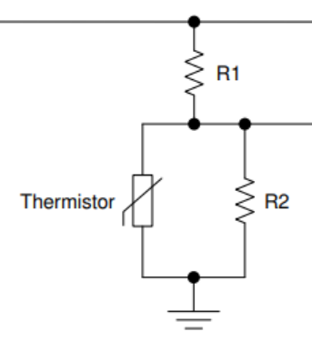
    The image below shows how I would expect the thermistor to be measured:

    • VDD_TEM in the customer's circuit is REFOUT in the image below
    • The thermistor in the customer's circuit is connected across J6
    • The 15k resistor in the customer's circuit is R1 in the image below
    • R2 is a linearization resistor, and is not strictly necessary

    Note that the customer is measuring across the thermistor, while the image below shows we are measuring across R1. Either is fine, because it is just a resistor divider.

    So I don't understand why the 10k resistor is necessary for the NTC (or the thermocouple)

    I would suggest using the configuration below where the ADC REFOUT biases the NTC. This will give you a ratiometric measurement if you also use the ADC internal VREF. If the internal VREF voltage drifts, the measurement will also drift and will cancel out. Using REFOUT will offer higher performance compared to using TL431, and it will be lower cost.

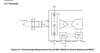
    For the thermocouple: you can reference this guide for more information (https://www.ti.com/lit/an/sbaa274a/sbaa274a.pdf?ts=1728660172939&ref_url=https%253A%252F%252Fwww.google.com%252F)

    Also, how is the customer measuring the cold junction for the thermocouple?

    -Bryan

  • The customer could use NTC to measure the cold junction for the thermocouple.

    Because the customer will use ADS12408 to sampling NTC and thermocouple at the time.

    Whether this kind of connection could measure negative voltage? 

    I guess it is OK?

  • Another question:

    Which solution have higher accuracy for NTC between "with R2" and "without R2"?

  • Hi Fabio Gou,

    I was not aware the customer will measure both NTCs and TCs at the same time. In your original post you said the circuits would be either TC or NTC, not both. Also the placement of the NTC at the cold junction is critical to the TC measurement accuracy 

    Whether this kind of connection could measure negative voltage? 

    Yes, this configuration can measure negative differential voltages: https://e2e.ti.com/support/data-converters-group/data-converters/f/data-converters-forum/1048636/faq-can-my-adc-measure-negative-voltages

    Which solution have higher accuracy for NTC between "with R2" and "without R2"?

    See section 2.8.2.2 in the document I linked to in my previous post (SBAA274)

    -Bryan