This thread has been locked.

If you have a related question, please click the "Ask a related question" button in the top right corner. The newly created question will be automatically linked to this question.

ADS8353: ADS8353 Single Mode Data Transfer Problem with Bit Banging

Part Number: ADS8353

Tool/software:

Hello,

We are trying to use ADS8353 IC in 32-CLK, Single-SDO Mode (CFR.B11 = 0, CFR.B10 = 1) with bit banging in software. We are using STM32 chip.

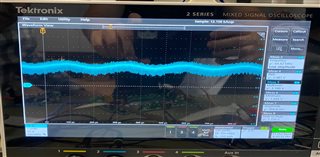
But the results from the IC is inconsistent. Raw ADC values changes every sample. Is this normal?

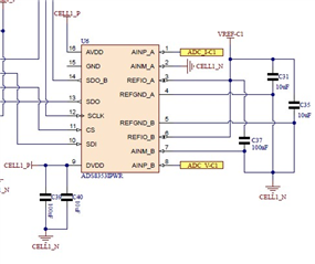
AINM pin is connected to ground. AINP pin is connected to our voltage supply(ADC V-C1 in the picture). VRef is 2.163 Volts. ADC V-C1(AINP) is 1.740 Volts when we measured it with multimeter. But ADS8353 output range looks between 1400-1900 after calculations. The supply voltage looks stable. 

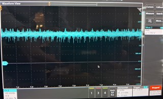
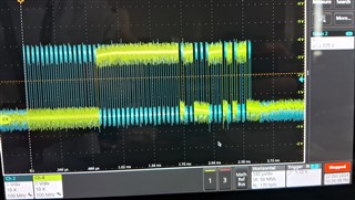
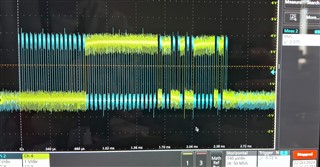
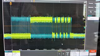
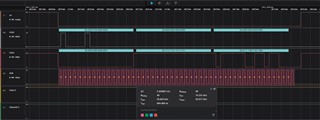
The result we get with Logic Analyzer and the schematic is in the pictures below.

Can you help us in this situtation, thank you.

  • Hi Ozgur!

    Welcome to our e2e forum!  It's not uncommon to see perhaps the two or three LSBs changing if you have constant DC source applied to the input.  In your schematic, you show pin 15 of the ADS8353 as 'open', is that really the case?  If so, that pin needs to be tied to ground.  The SDO shows the conversion result of CHA to be Full Scale (0xFFFF) so I'm not quite sure where this 1400-1900 value you calculated is coming from.  With 1.74V in, the output code (assuming you are in 0-Vref mode) should be around 0xD089.  If pin 15 is truly not grounded, you can and will see some strange behavior so hopefully it's that simple of a fix for you.

  • Hello Tom,

    Thanks for quick answer. Pin 15 is actually connected to ground. If i'm not mistaken the first 16 bits after conversion starts shows SDO-A which is our ADC_I pins output. In the picture that 0xFFFF in SDO-A is due to our hardware at that moment. 

    While measuring SDO-B output, instead of 0xD089 like you mentioned, we get results fluctuating in between 0x8AAC and 0xEA60 in hex format. So as you said if two or three LSB changes, the fluctuations should not be this much right? Some MSB bits of the output changes each measurement when we look at it with an oscilloscope.

    Yes IC is in 0-Vref mode. Might there be a problem with configuration? Or anything about the ADS8353 schematic?

  • Are you able to measure the B input voltage with an O'Scope?  If there is any ripple/oscillation on that input voltage, a multimeter won't be able to catch that.

  • Yes we are, sorry for the delayed response. Here is the B input voltage on the oscilloscope

    and some sample results from clock and sdo pins

  • Hi Ozgur,

    You are sampling relatively slow, so even with the noise on INB, I wouldn't expect that much code variation.  Next debug steps would be to check how clean your reference voltage is.

  • Hello, we were in a little holiday season in Turkey so i can write just now.

    We checked VRef signal in PCB and it looks sinusoidal as seen in the picture. We are using MCP1501 IC's output as VRef and investigating the issue here. While my coworker is working on that, we wanted to write about this. 

    May this be the reason of unstable results or may it be something different?

    Thanks in advance.

  • It absolutely can be the root cause of the issues you are having.