This thread has been locked.

If you have a related question, please click the "Ask a related question" button in the top right corner. The newly created question will be automatically linked to this question.

ADS7809: driving the analog input: unipolar operation 0 to +5V

Part Number: ADS7809


Tool/software:

I'm planning to drive the ADS7809 analog input in unipolar config:  0 to +5V.  We're using this part to monitor temperature sensors. 

The circuit topology is as follows:

1.  Will have 2 16:1 analog muxes to bring in the pair of signals for a given sensor

2.  Next I'll have an instrumentation amplifier with gain = 1.  Will take the pair of signals and generate a single-ended output

3.  Low pass filter (passive RC circuit)

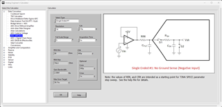
4.  Op amp voltage buffer (TBD) to drive the ADC analog input

Main question involves #4:  what are the requirements of the op amp used as a buffer circuit to match the ADC analog input?  The voltage should be 0 to +5V coming in and going out of the buffer.

If you have any other comments on the overall circuit topology, please let me know.

  • Hi Erik,

    We have a tool in the Analog Engineer's Calculator that helps you pick an appropriate amplifier for driving SAR converters.  The ADC SAR Drive tool lets you put in your desired acquisition time and a few parameters from the datasheet.  The ADS7809 goes into acquisition mode after the current conversion is complete (see Figure 1).  If you are running the device at its fastest speed, you would have 2uS of acquisition time - if you are running the part slower, that acquisition time will increase.  So, with the 35pF sample/hold capacitor and 2uS of acquisition time, you would be looking for an amplifier with 2.6MHz GBW.