This thread has been locked.

If you have a related question, please click the "Ask a related question" button in the top right corner. The newly created question will be automatically linked to this question.

ADS5271: Vcm output abnormal

Part Number: ADS5271


Tool/software:

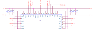
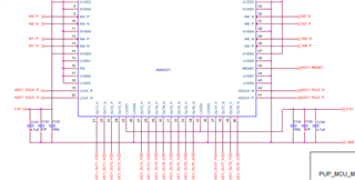
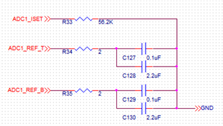
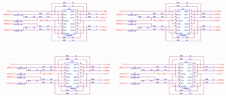
I made 20 boards using ADS5271. The Vcm outputs of 16 boards are around 1.45V, otherwise, the Vcm of the other 4 boards are between 0.36-0.6V. Among the 4 boards,  2 boards go back to 1.45V when quickly repowers the boards, and the other 2 boards keep the same wrong outputs. Can anyone help explain how to solve the problem?

  • By the way, I set it as an internal reference with PD=0 and Next=1. In all cases, the RefT is around 1.94V, and the RefB is around 0.94V. This phenomenon happened to my other design two years ago, and I had to create Vcm using a ladder for external Opam.

  • Hi,

    Sorry for the issue, can you please send over your schematics so I can make sure everything is properly connected?

    Also, please send over the spi writes that you are using to configure the device/ADC.

    Thanks,

    Rob

  • Thanks, Rob

    Above are the schematics I used. Default settings are used for the application. I didn't use SPI to change new settings. I checked the pins: PD=0, INT/EXT=3.3V, RefT=1.945V, RefB =0.945V. Vcm=1.45V for 16 boards, Vcm=0.36V for 2 boards, Vcm=0.53V for 1 board, Vcm=0.62V for 1 board.

    2 boards can turn out to be normal using a power cycle, but the other 2 can't.

    I can capture the correct data from the chip, the problem is the Vcm output is not correct and can not be used for external Opam for those abnormal boards(1 out of 5). (The layout  was already designed to use it.)

    After I disconnected the Vcm output and added a voltage ladder to create 1.45V for external Opam, the boards worked fine. Just the problem confused me for a while.

  • Hi,

    It would be best to have a opamp follower/buffer in order to drive all the THS amplifier VCMs. The drive strength of the ADC's VCM is not that robust to drive the VCM load of all these THS amplifiers.

    You can prove this to yourself by removing a few of the THS amplifiers from the VCM connection and only allowing one or two amplifiers on the VCM connection to see if your data capture works for those channels.

    Unfortunately, you will need to use a buffer opamp.

    Regards,

    Rob

  • It is the driveability problem. Although the datasheet specifies a typical 2mA output, some chips may not be robust enough to drive an 8x0.02+mA load.

    Thanks.