- Ask a related questionWhat is a related question?A related question is a question created from another question. When the related question is created, it will be automatically linked to the original question.
This thread has been locked.
If you have a related question, please click the "Ask a related question" button in the top right corner. The newly created question will be automatically linked to this question.
Tool/software:
Hello TI experts,
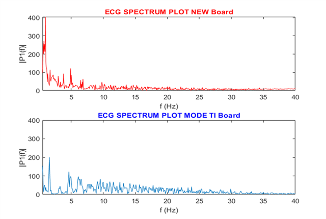
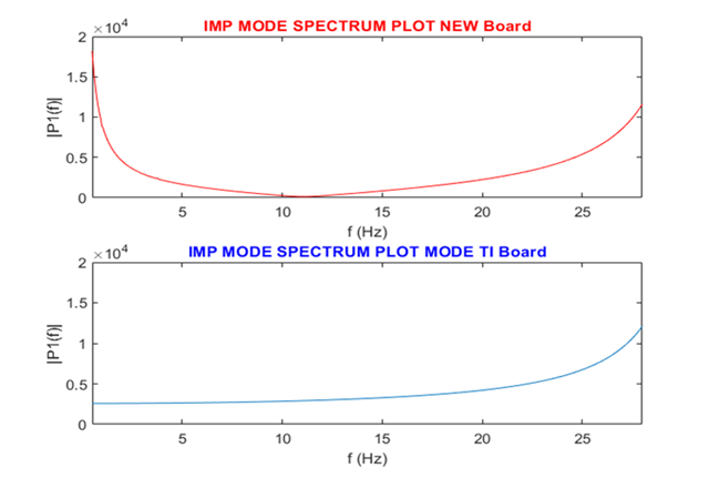
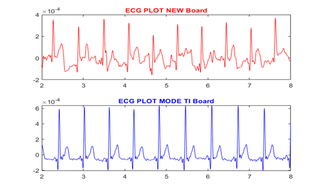
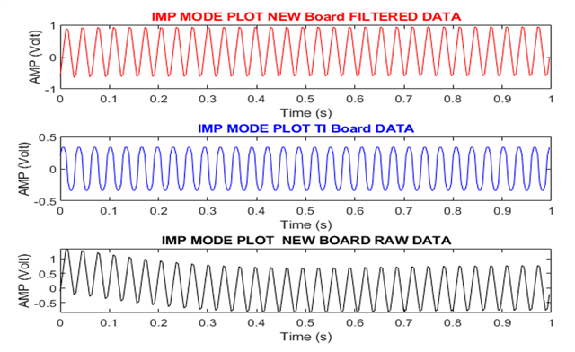
Its a long time to get expertise after finished Impedance measurement and jumper setting of ADS1299 EVM board. Now we have have developed a PCB using ADS1299 and getting a strong DC noise with initial transients during impedance mode and an strong noises at low frequencies in ECG mode as well as Impedance testing mode. Figure 1 and Figure 2 two shown an spectrum plot on ECG signal and impedance mode for low frequency signal. While time domain ECG signal plotted in figure 3 and impedance mode signal plotted in Figure 4 respectively.
Any comments from the experts behind the reason this noise in the new designed circuit will be quite helpful and appreciable. While the new design replicated from the same schematics as used in ADS1299 FE PDK evaluation board only LPF response antialiasing filter components values changed Resistor to 3.3K instead 4.99k and Capacitor to 47 nF instead 4.7 nF as per ADS1299 FE PDK EVM Board, to reduce the lower cut-pff frequency to 1000 Hz.


Kindly leave your valuable comments to proceed for the discussion on forum and feel free to get back to me if needed any additional information.
Regards,
Hello ID,
Thank you for your post.
If you apply an external short between the channel inputs and force a common-mode voltage, how much offset are you measuring on your PCB vs. the TI EVM? It may be there is some mismatch in the input impedance from trace routing our component tolerance.
Regards,
Ryan
Hello Ryan
I got your point. Since I do not have similar jumper setting option (JP25, JP6, JP7, JP8) left open pins on my new (customized) board, So I need to go for soldering on PCB. My point was, what if I do measurement on common reference on negative inputs as mentioned into section 8.3 usar manual of ADS1299 FE PDK.
Is that ok to use any option to calculate DC OFFSET as mentioned in section (8.1, 8.2, 8.3) in the user manual as per our setup (customized board) convenience.
Gracias and regards,
Hello ID,
The measured offset may differ slightly between the INxP-INxN differential input vs. INxP-SRB1, but they should be reasonably close together. The reason for the difference is that the input impendence seen through the SRB1 pin into the PGA differs slightly compared to the normal input pin.
Regards,
Ryan