


Tool/software:
Good afternoon,
I'm having trouble initializing TPL1401 digital potentiometer, specifically trying to write GENERAL_CONFIG register and DPOT_POSITION register. Let me add some more context.
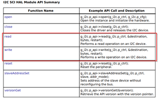
Like in my previous post I'm using e2_studio programming IDE, and I'm using synergy S7G2 micrcontroller, e2_studio provides low-layer drivers that controls in the background I2C addressing + R/W! bit, meaning you specify a 7 bit device address and then, depending on which method user uses (write/read), R/W! bit is set to 1 or 0 :
Reading TPL1401 datasheet, Address Byte is 8 bit long, AD6 AD5 AD4 AD3 AD2 AD1 AD0 R/!W, acording to datasheet first 4 bits are fixed (1001), following 3 bits depend on A0 pin, since I'm controlling 16 TPL1401 I have all possibilities:
000
001
010
011
Lastly, as mentioned before R/W! which is controlled using I2C low-layer methods. Knowing I have to set an Slave Address, all possible combinations are the following:
0x48 (1001 000) 7 bit long
0x49(1001 001) 7 bit long
0x4A(1001 010) 7 bit long
0x4B(1001 011) 7 bit long
If I want to perform I2C Update Sequence I need to send Address Byte + Command Byte + MSDB + LSDB (32bits), e2_studio manages first 8 bits in the background, so me as user i only have to send 24 bits.
If I want to perform I2C Read Sequence I need to send Address Byte + Command Byte(write request), then send a read request and store whatever TPL1401 returns.
Now, I could validate reading TPL1401 STATUS register and GENERAL_CONFIG register. When I try to read mentioned devices I get the following:
STATUS : 0000 0000 0001 0100 --> 0x14 which matches device_id[5:2] value
GENERAL_CONFIG: 0000 0001 1111 0000 -> which matches default configuration, DPOT_PDN[4:3] field is initialized to 10 (Power down to high impedance)
I assumed because of this I'm not able to write/read DPOT_POSITION register, so the logic thing would be to set DPOT_PDN[4:3] to 00: Power Up, problem is when I try to write this register it doesn't seem to be able to set desired value.
GENERAL_CONFIG is 16 bit long, so I assumed the correct register configuration would be 0000 0001 1110 0000, this can be placed inside a uint8_t array of two positions, for example
//TEST
data = 0xE0;
uint8_t i2c_data[2] = {0x01, data}; // MSB = 0x00, LSB = data
When I call my i2c method it seems to be performed correctly, but when I try to read the register it is still the same as the beginning, no changes are applied, so I'm wondering what I could be missing, I can provide the whole code if necessary.
In resum, my write petition is 24 bit long, Command Byte + MSB + LSB, but when reading same register value stays unchanged.
Greetings,

