Part Number: AFE58JD32
Other Parts Discussed in Thread: TX7364
Tool/software:
Hi,
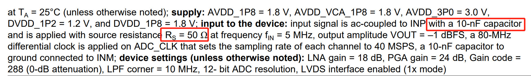
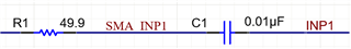
I’ve been using the AFE58JD32 (EVM) recently, and I noticed that in the provided schematic, each INP pin is connected to a 49.9 Ω resistor and a 10 nF capacitor. This seems to match the test conditions specified in the datasheet: “INP with a 10-nF capacitor and is applied with source resistance RS = 50 Ω at frequency fIN = 5 MHz.” My question is, does this RS need to be adjusted based on the load?
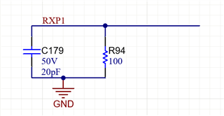
Similarly, when using the TX7364 (EVM), I encountered the same issue. The datasheet specifies the load as being “Connected to the pulser output is 400Ω||125pF, and to the T/R switch low voltage output is 100Ω||20pF.”
If my load is 300Ω||200pF, how should the output of both chips be adjusted?
Thank you for your help!
Best regards