This thread has been locked.

If you have a related question, please click the "Ask a related question" button in the top right corner. The newly created question will be automatically linked to this question.

ADS1015: Liquid leakage sensor amplifiers design

Part Number: ADS1015
Other Parts Discussed in Thread: ADS1014

Tool/software:

Hi Sir.

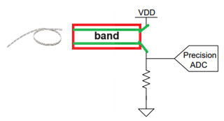
I want to do a liquid leakage sensor amplifiers design and find out the ADS1015 can do that from the TI application brief.

https://www.ti.com/lit/ab/snaa422/snaa422.pdf?ts=1730816492789&ref_url=https%253A%252F%252Fwww.google.com%252Furl%253Fq%253Dhttps%253A%252F%252Fwww.ti.com%252Flit%252Fpdf%252Fsnaa422%2526sa%253DU%2526sqi%253D2%2526ved%253D2ahUKEwjqlaHsscWJAxWXma8BHWEZNgIQFnoECB8QAQ%2526usg%253DAOvVaw07AH4ZsyyVVSn7Wo7wu73P

For the sensor band, I will use Omron F03-16PE band.

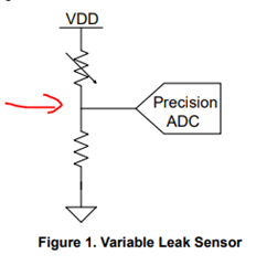
In Resistive-Based Leak Sensors section, the ADS1015 ADC can implement it.

I don't know how to design it? Can you share more detail information to me? Include reference design, appliction note..etc.

Thanks

  • Hi Yeh Elvis, 

    As of right now we only have the above mentioned technical note. We are working a technical application note, but release will not be until 1Q25. 

    The basic premise is when leakage is detected by the resistive leak sensor the voltage in the leak detection circuit will change accordingly and the ADC is used to monitor for the change in voltage.  

    The ADC simply measures the sensor voltage as it would in any regular voltage divider.

    Best Regards,

    Angel

  • Hi Angel,

    Understood.

    If follow the document, replace resistor with sensor band.But I have one questions.

    I measure the band resistance value without water on the band by mulimeter and the value around 11Mohm~13Mohm, And resistance value around 5Mohm~7Mohm with water leakage on the band. If follow the reference design, it means the resistance value around 11Mohm~13Mohm or 5Mohm~7Mohm between VDD and ADC. When resistance value changed, the ADC will detect the voltage on variation.

    The resistance value is always on variation(11Mohm~13Mohm or 5Mohm~7Mohm). It menas the voltage is always on variation at ADC site.

    How to know the voltage variation is cause lthe eakage? Because the resistance value is not with gap value when leakage.

    Thanks 

  • Hi Yeh Elvis,

    It seems like there is a range for the resistance values when there is no leakage (11Mohm~13Mohm) and when there is leakage (5Mohm~7Mohm).

    This means you could simply set some threshold depending on these values.

    For example, if resistance is higher than 10Mohm there is no leakage detection, if resistance is lower than 8Mohm there is a leakage detection.

    You can select what the thresholds would be depending on your sensor measurements.

    Best Regards,

    Angel

  • Hi Angel,

    Yes. that's what I think too.

    I had study ADS1015 spec yesterday, I thinks that can use alert singal to do the alarm.

    The alert can config threshold value. When leakage detected, alert will delive Hi or Lo to CPU.

    I have discuss with local TI FAE and he will provide EVB board to me and test it after get EVB board.

    If have any quetsions I will let you know.

    Thanks

  • Hi Yeh Elvis,

    This sounds like a valid approach. Feel free to reach out if there are any more questions.

    Best Regards,

    Angel

  • Hi Angel,

    The ADS1015 is 4xCH and they are MUX function, not a independent function. It's meants that only detect 1x leakage at the same time.

    Even if connect 4x leakage band, we still need change the channel to know the band whether leakage or not? 

    And the threshold of alerm is same value on this 4xCH. Is it correct?

    In my application, I need connect 3x leakage band, So I thinks that should be use 3x ADS1014, it's 2xCH with 1x alert.

    The CPU can receive alert signals from ADS1014 at the same time for this 3x leakage band.  

    Thanks

  • Hi YEH ELVIS,

    Angel is out of the office today, we will respond to you in the next 1-2 days

    Thanks for your patience

    -Bryan

  • Hi Yeh Elvis,

    Even if connect 4x leakage band, we still need change the channel to know the band whether leakage or not? 

    Correct, you would need to change the channel/mux setting to read the different inputs/leakage bands.

    And the threshold of alerm is same value on this 4xCH. Is it correct?

    Yes, the threshold for the alarm pin would be the same for the 4x channels. However, you could change the threshold settings by writing to the Lo_thresh and Hi_thresh registers every time you write to the configuration register to change the MUX channel setting.

    In my application, I need connect 3x leakage band, So I thinks that should be use 3x ADS1014, it's 2xCH with 1x alert.

    I agree that probably the best solution is to simple use a separate ADC for each of your leakage band sensor measurements, as this allows you to monitor all 3 of them at the same time rather than having to cycle through the mux and change your settings every time.

    Best Regards,

    Angel

  • Thanks for your response.

    If have others questons I will let you know.

    Thanks