This thread has been locked.

If you have a related question, please click the "Ask a related question" button in the top right corner. The newly created question will be automatically linked to this question.

ADS9219EVM: One Lane, DDR mode support - Is Data Averaging required ?

Part Number: ADS9219EVM
Other Parts Discussed in Thread: ADS9218, ADS9219

Tool/software:

Dear Sir/Madam,


We are testing ADS9219EVM currently. It appears that Ads92xx_EVM_GUI software automatically enables the OSR2 filter while capturing the ads9218 data on 1-lane, DDR mode. 

Is it an expected behavior of ADS9218 ADC? Is it possible to get the 10 Msps output from ADS9218 ADC on 1-lane, DDR mode? 

Kind regards, 

Panneer Raja Vajravelu

  • Hello Panneer Raja, 

    Thank you for your question!

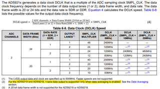
    Yes, for the ADS9219 and AD9218 due to the faster sampling speeds (10MSPS and 20MSPS) 1- lane data output is only supported when data averaging is enabled. 

    Please let me know if there is anything else I could help with when evaluating these devices. 

    Best regards, 

    Yolanda

  • Hello Yolanda, 

    Thanks for the reply. 

    Is Note 2 mentioned in the below table applicable to 24-bit data frame, DDR, 1-lane, 10 MHZ MHz sampling frequency settings? 

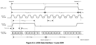
    According to the below timing diagram, 

    2-channel, 1-lane, DDR, 10 MHz data output seems a possibility, right? Why is then an averaging required?

    Kind regards, 

    Panneer Raja.

  • Hello Panneer Raja, 

    Both are very good questions that bring up some corrections/additions needed in the datasheet, thank you for bringing this up. 

    For your 1st question, Yes, it is applicable for the 24-bit, DDR, 1-lane, 10MHz sampling rate, the note superscript should appear on the rows where data lines is equal to 1. There seems to be some changes needed on that table. I will submit a change for the datasheet to address this. 

    And for the 2nd question, this has to do with the frame clocking (FCLKP/M), at 10MHz sample clock the minimum FCLK high time is ~50ns and for 20MHz it is ~25ns this is what it ends up being in 2-lane DDR. When in 1-lane DDR that value would technically be divided by 2 and would therefore be below the minimum, so since enabling averaging slows down the FCLK, it is required to be able to reach the minimum FCLK high time needed. 

    Do you have a need for a 1-lane output at 10MHz?  Having a 1-lane DDR at 20MHz (with averaging) could provide a similar throughput.


    Please let me know if there are any more questions regarding the device or anything else I can help with for evaluating the ADS921x devices for your design. 

    Best regards, 

    Yolanda 

  • Hello Yolanda, 

    Thanks for the reply. 

    We can only operate on 1-lane mode because our Fpga data capture board has only one lane per ADC. 

    Yes, we shall run the ADC at 1-lane, DDR, 20 MHZ sampling rate to get the 10MHz data throughput. Thanks for the Idea.

    Because of the limitation in the fpga data capture board, we have to generate the FCLK and DCLK in the fpga itself and acquire the data in System synchronous mode. By doing so, can the 10 MHZ data throughput be achievable for 1-Lane, DDR, 10MHz sampling rate settings, if data averaging registers are not set automatically?

    Kind regards, 

    Panneer Raja. 

  • Hello Panneer Raja, 


    Unfortunately 1-lane is not supported with a 10MHz sampling clock without data averaging being enabled. I would recommend using the ADS9219 with a 20MHz sampling clock and data averaging enabled to achieve the 10MSPS in 1-lane DDR mode.

    Best regards, 

    Yolanda

  • Hello Yolanda, 

    "Selected device doesn't have this feature" message gets thrown out while trying the ADS9219, 20MHz, 1-lane mode, OSR2.

    Found another Bug when using the ADS9219. On ADS9219, 20MHz, 1-lane mode, OSR2 mode, Channel 2 has the same data as Channel 1. 

    ADS92xx_EVM_GUI.exe blocks the 20MHz, 1-lane mode, OSR2 mode of operation or ADS9219 does not support this mode?


    We would like to verify our system synchronous mode (Self-clocked mode) in the Ads9219EVM + TSWDC155 test setup. 

    Therefore, it would be great if you could provide us with the following, 

    a. Schematic of TSWDC155 fpga data capture board.

    b. FPGA project and source codes for Artix 7 FPGA. 

    Kind regards, 

    Panneer Raja. 

  • Hello Panneer Raja,, 

    Please see the Other E2E post for the response to this question. 

    Best regards, 

    Yolanda Gonzalez