Tool/software:
Hello Experts,
We are currently using the AMC1303M0510 to measure two phase currents in our custom motor driver board using the TMS320F28379D 's SDFM module.
This is how we are measuring the phase currents:
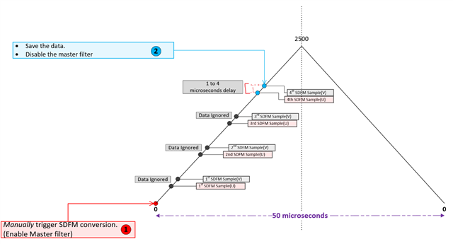
- The SDFM data filter is configured with a OSR of 58 , in 16 bit mode and the Acknowledge interrupt is enabled.
- Once the PWM ISR is triggered, we start the SDFM's data filter.(MFE bit is 1). [PWM sync is not used.]
- In the SDFM ISR, we ignore the first 3 samples and save the 4th sample. This is done for all the two phases. Every measured sample is captured after polling the Acknowledge bit of the respective filter Chanel. Once all two phases data are captured , the individual filter channel interrupt and the Master filter interrupts are disabled(MFE bit is 0.)
Here is a brief diagram explaining the timing , w.r.t the PWM timer

One observation here is that , even though the MCU's data sheet states that all the filters are synchronized to the Master filter enable bit, we always see that the two phase's data are not captured simultaneously,(The acknowledge bit of both the SDFM filter channels are never set at the same time.)..There is a delay of about (1 to 4 microseconds) between the two measurements.

We still are able to run our motor controller, but with a slightly higher currents and a higher torque ripple. We think this measurement delay may be the root cause.
So my first question is , using the AMC1303, how do we ensure that the data is measured simultaneously.
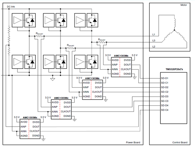
Secondly, Is this delay coming in because the AMC1303's clock are not synchronized?
Looking at the AMC1303's data sheet, we notice that the AMC1303's CLKOUT pins will never be in sync with each other, which may cause this delay?

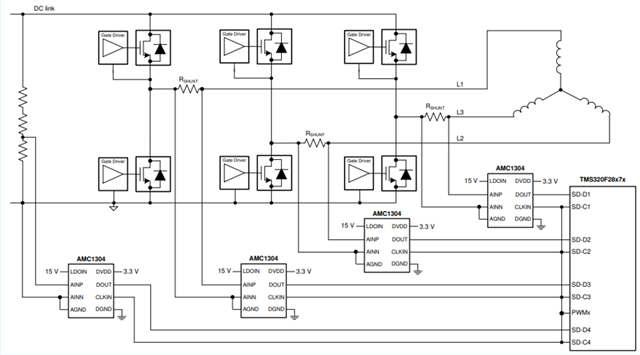
Also looking at the the AMC1304M25DW 's typical application , we see that the Clocks for all the AMC's are provided by the MCU itself, which will assure that all the clocks are synchronized?
If we were to switch over to using this modulator, would this guarantee simultaneous sampling?

If the above analysis is correct, could you please shed some light on the correct use cases of the AMC1303 and the AMC1304 with respect to a Motor driver application.
Thanks!


