ADC34J45: Digitalized signal with high phase noise

Part Number: ADC34J45

Tool/software:

Dear sirs,

I am working with ADC34J45 and I have a problem related to the phase noise with the digitized signal.

Configuration of ADC34J45 is shown as follows:

- Input frequency = 47.4 MHz -20dBm Without modulation

(-84dBc to 25KHz offset with BW=25KHz)

  • Frequency clock: 158.4MHz LVDS Level about 0 dBm to the input of ADC

(85dBc adjacent channel to 25KHz offset (BW=25KHZ))

But the signal digitized by ADC is showing a high phase noise and very bad adjacent channels 

Please, find below the digital signal analysed with MATLAB.

Zoom in 47.4MHz:

As you can check, phase noise is very bad in comparison with the phase noise of input signal and the clock signal.

I have checked the power supply increasing the DC filter to the input of low noise LDO which is used to supply +1.8AVDD to the ADC. I am using LDO from Texas TPS7A9101DSK.for 18AVDD.

Please, find attached a file with the samples of ADC, the values in the file are multiplied by 4 related to the output of ADC.

BufferRxData_B.txt

Finally, the inoput impedance of ADC is 200 ohms, and therefore the 0dBFS is about +4dBm.

Please, could you help me witth this issue?

Thanks in advance.

Best Regards,

Pedro

  • Hi Pedro,

    If you are using Matlab, then its plotting the real and imaginary portions of the FFT.

    The high phase noise, is not really the issue, you are probably using a frequency that is not coherent or bin-centered.

    One way to get around this is after you take the FFT, apply a Hanning or Blackman Harris window function in Matlab.

    Or you can bin-center your input signal in order clean up the FFT.

    To learn more on coherent and non-coherent sampling. Please refer to the following link:

    www.planetanalog.com/.../

    Thanks,

    Rob

  • Hi Rob,

    Thank you for your feedback.

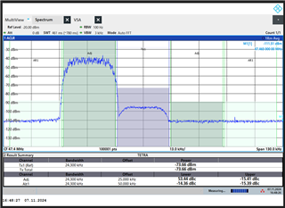
    I am checking the phase noise, because i am testing the adjacent channel rejection of a receiver and this is very poor. When a signal in adjacent channel of desired signal is higher tha 40dBs related to desired signal, the receiver is not able to decode the desired signal and I think that this is due to the phase noise  generated digitally in the desired channel by the interference signal in the adjacent channel.

    I have checked this situation in the ADC input and the signals are right (see image below), but the adjacent channel rejection is very bad and checking phase noise of digital signal , this is very bad. I am analyzing directly the samples of ADC converted in volts using Vpp=2V and 14 bits resolution.

    a) analog signal in the input of ADC


    b) Digital signal in the output of ADC

    Thanks in advance.

    Best Regards,

    Pedro

  • HI Pedro,

    Lets start with a single tone frequency first.

    Are you coherently sampling? We need to make sure your test setup is good first.

    Thanks,

    Rob

  • Hi Pedro,

    I second Rob's suggestion above. If you are not coherently sampling the signal, then bin leak will occur around the fundamental and you will see this elevated skirting look in the FFT. You can also implement some form of digital windowing, such as hanning or blackman-harris onto the time domain codes before you process the FFT.

    Thanks, Chase