Other Parts Discussed in Thread: ADS1115
Tool/software:
Hi all,
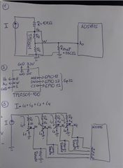
I am using the TPL0501 to control the current through the branches of a current divider, aiming to equalize the resistances and maintain the same current in each branch. The potentiometer schematic is as follows:
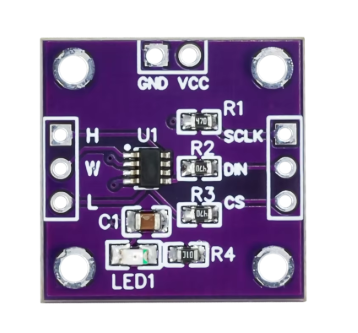
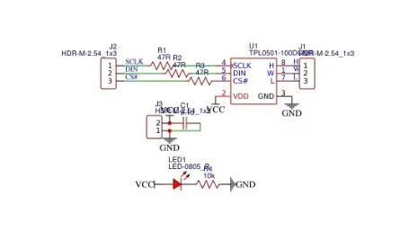
My problem is that when using a current source and having two branches with a potentiometer + a fixed resistor, if the potentiometer is set to a value lower than the fixed resistor, it ends up taking all the voltage, causing VH to exceed its limit of VDD+0.3V, with VDD currently being powered at 3.3V.
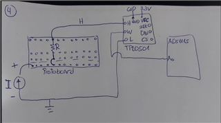
The SPI communication is working correctly, as I have connected W to an ADS1115 ADC where the voltage change can be observed when varying the values. Additionally, H is connected to a fixed 10k resistor, which is connected to the current source that supplies 2mA and provides a voltage range between 0 and 34V. Finally, L is connected to ground because I am using the configuration as a voltage divider.
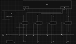
I tried placing a voltage divider between the 10k resistor and the potentiometer to keep the VH range between 0 and 3.3V, but the system still doesn't work. I have the following schematics of the connections I am using on my PCB. Here, I am using 4 TPL0501 potentiometers, an ADS1115 ADC, and an ESP32:
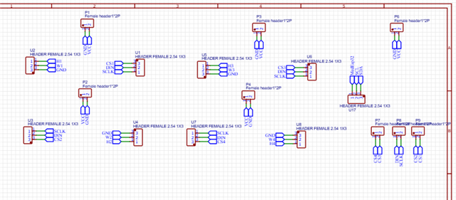
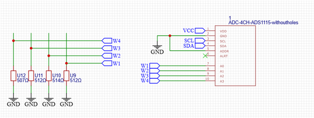
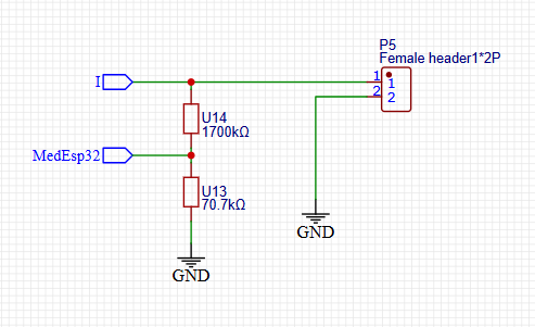
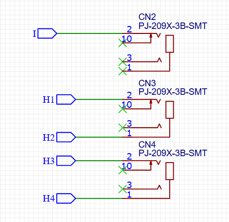
It is worth mentioning that I am using Jack input electrodes, where I is connected to a breadboard containing the 10k resistor, and each H is connected to the other end of this breadboard.
Best regards
Felipe.


