Tool/software:
Hello, I have created a new PCB board with MCU and DDC264. I wanted to establish communication via SPI and start reading data. Currently, I want just only check that my design is correct.
In my vision, I want to read data without writing any registers.
So does it work the next protocol to read data?
I connected the next pins via the SPI protocol
- SPI CLK (MCU) to DCLK
- MISO (MCU) to DOUT
- GPIO input (MCU) to DVALID
So what was done from me
1. Wait when via GPIO (MCU) when DVALID fall down from 1 to 0
2. Make a command to read via SPI 128 bytes
This is right?
Regards, Ildar 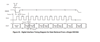
Regards, Ildar