ADS124S08: ADS124S08 Floating Inputs Getting Error

Part Number: ADS124S08

Tool/software:

I used ADS124S08 in my design. When the input is connected to a known value, it gives the correct value. Although there is a pull down resistor connected to the input pins, it does not give '0' in the floating state and we see values ​​with a lot of difference between the min/max values. How can we reach the 0 value in the floating state?

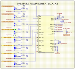
The circuit diagram is as follows

  • Hi Mesut Can Yaman,

    Can you please share a complete schematic?

    Also what inputs are you using for MUXP and MUXN? Are they both floating?

    It would probably be helpful to see your register settings and ADC output data as well

    -Bryan

  • Hi Bryan,

    The complete schematic diagram is as follows.

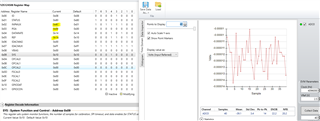
    Let me explain the problem in more detail; I have sensors that output 4-20mA, 0.5V-4.5V connected to my single-ended measurement lines. I can measure properly when the sensors are connected, but when I disconnect the sensors, I see meaningless data. This should not happen because I have a hardware pull-down resistor. The information about PGA VBIAS and burn-out sources is as follows. Can you help me with this issue?

    Mesut Can 

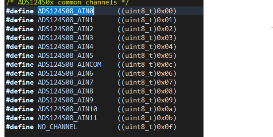
  • Also, we set the register for MUXP and MUXN as follows:

  • Hi Mesut Can Yaman,

    You should leave VBIAS and the burnout current sources off, they are not needed in your system as far as I can tell

    What values are you actually measuring at the ADC output when you say "meaningless data"? I asked for this info in my last reply but you did not provide it

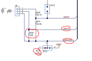
    I tried taking similar measurements on the EVM, using the AIN11 and AINCOM pins below (you can see that there is a 100ohm resistor between inputs, similar to your 120ohm). I left J9-2 unconnected, and below is the measurement data I received. You can see that this looks a bit like noise, I suspect this is due to the leakage current from the ADC flowing through the resistor. So you are actually getting a very small voltage measurement on the input, and therefore there is some variation in the measurement due to noise.

    -Bryan

  • Hi Bryan,

    When I take measurements with an oscilloscope, I see a noisy signal with a peak to peak of 20 mV. When I look at it as raw data, I see data that changes instantly and fluctuates between hundreds of thousands and millions. The signal coming to the integrated circuit is correct, but there seems to be a problem with the raw data that the integrated circuit converts and gives us. Do you have any suggestions on this?

    Since it is evening hours in Turkey, we could not try the register map you sent.

    Mesut Can.

  • Hi Mesut Can Yaman,

    When I take measurements with an oscilloscope, I see a noisy signal with a peak to peak of 20 mV.

    Are you measuring this at the ADC input pins? If so, the ADC is going to report back the voltage reading at the inputs, which is ~20mV. Can you please provide the scope shots of the signal you are measuring?

    When I look at it as raw data, I see data that changes instantly and fluctuates between hundreds of thousands and millions

    Can you provide the raw data you are measuring?

    -Bryan