Tool/software:
Hi ti team,
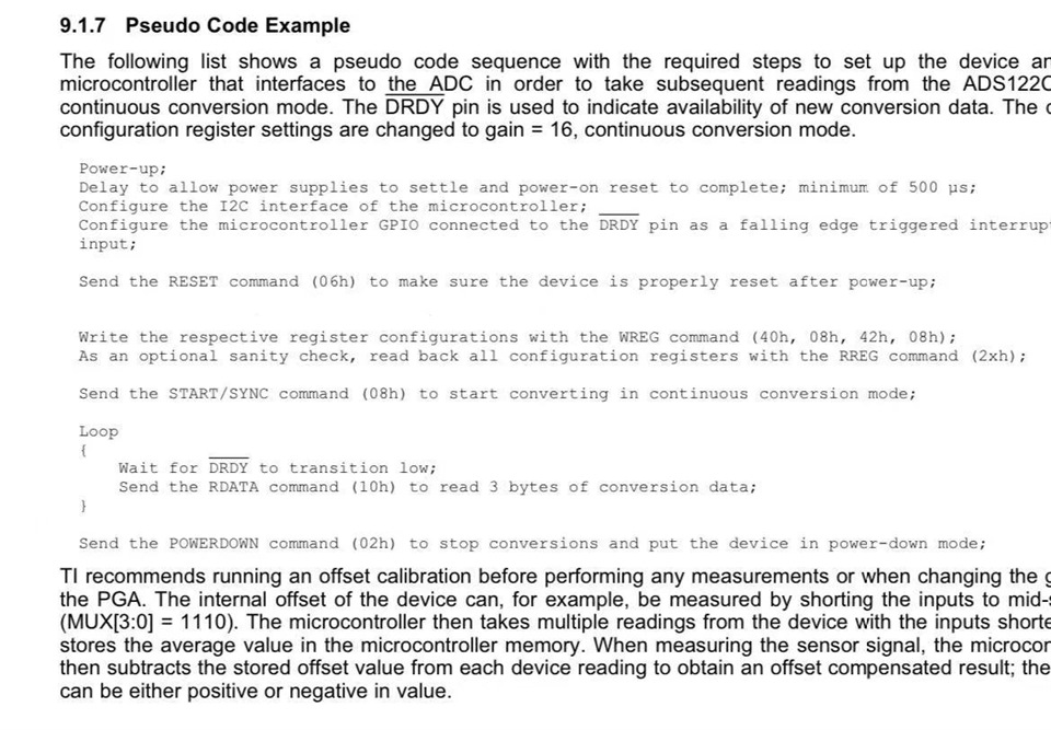
We recently used TI's ADS122C04 ADC chip, and we found that its DRDY pin does not pull low after data conversion, please help analyze what the reason is?
The software code is written according to the screenshot below.
Tool/software:
Hi ti team,
We recently used TI's ADS122C04 ADC chip, and we found that its DRDY pin does not pull low after data conversion, please help analyze what the reason is?
The software code is written according to the screenshot below.

Hi switch,
Is the DRDY pin connected to DVDD using a pullup resistor?
Best Regards,
Angel
Hi Angle,
What kind of problems might you think be? Is it software configurable? What information do you need from me to judge?
Best Regards,
Winnie
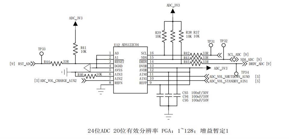
Is there a schematic that you can share?
Also, can you take captures of the digital communication to the device with a logic analyzer or an oscilloscope when doing a data conversion read?
Best Regards,
Angel
Hi Angle,
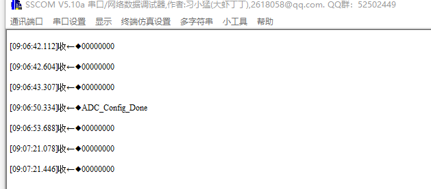
The I2C waveform cannot be measured, and the I2C communication will be abnormal when connected to an oscilloscope, If you manually connect DRDY to GND, I2C will return a value, but the return value is all 0 (at this time, the channel input voltage is 3.3V).
Schematic diagram
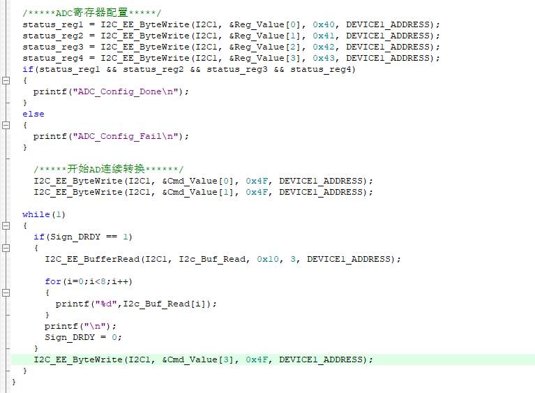
This is our program setup.

Hi Switch,
The schematic looks ok.
Probing the actual communication lines is very useful when debugging, as it allows to verify that what you are intending to send with your code is actually being received by the ADC.
Why can't the I2C waveform be measured and why would the I2C communication be abnormal when connected to an oscilloscope?
Best Regards,
Angel
Hi switch,
Section 8.5.2 of the data sheet shows how to convert between input voltage and the ADC's output code:
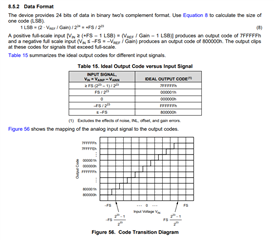
We have ADS122C04 example code available here:
ADS122C04-C-EXAMPLE-CODE Support software | TI.com
Best Regards,
Angel