Because of the holidays, TI E2E™ design support forum responses will be delayed from Dec. 25 through Jan. 2. Thank you for your patience.

ADS124S08: ADS124S108 Single ended measurement errors

Part Number: ADS124S08

Tool/software:

Hello Team.

We are using ADS124S108 for measurement of PTC1000 based temperature sensor in 3 wire configuration. 

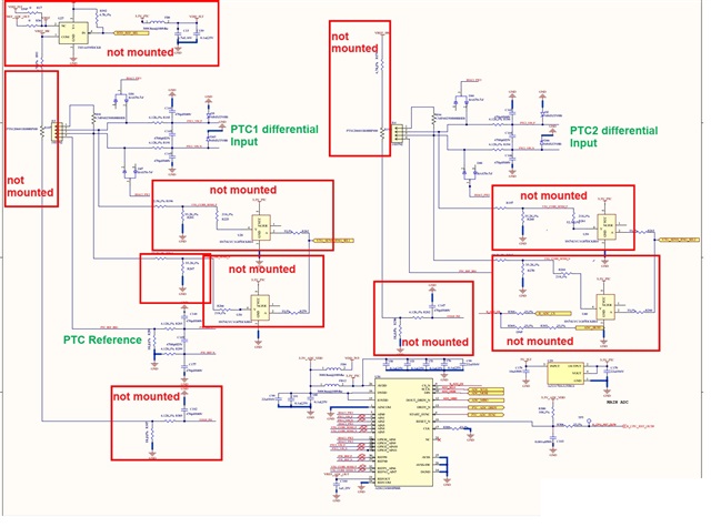
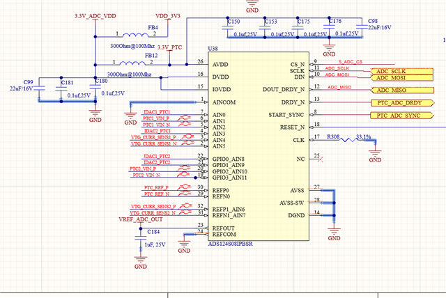
Attached schematic for your reference.

For  board bring up i did following tests :

1. First testing each analog channel in single ended mode by tying pins internally using the  Vbiase setting and checked . (Avdd+Avss)/12 and  (Avdd+Avss)/2

It can be seen the accuracy is near +/- 1mV or better. So i tested channel 0 to 5 in this manner . Same way tested the differential mode and accuracy was similar. Please note during this testing i disconnected all external ckt so that there is no loading on these pins.

2. In next step all Vbiase were turned off and we gave analog input to one of the channels ( AIN1 ) using a unity gain opamp externally and captured the ADC codes in single ended mode .. Below are the observations.
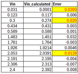
Note that in this case also we kept all other Analog channel pins floating.  Below are the resistor values configured for this evaluation.
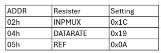
So i have two queries here :

1) why we are getting so much variation in measured vs actual input when we give input from external source as compared to when the input is given using Vbiase.

2) we are planning to use this 24bit ADC in an application where we expect a temperature resolution is 0.1 C with PTC1000 , please guide us is there is any thing we are missing 

Regards,

Santosh   

  • One more input , during step 2 of testing , the remaining register settings are not changed 

  • Hi Santosh Jadhav,

    Why do you assume that the ADC is the issue here? You mentioned that the ADC worked fine during the initial tests, then you added a buffer, and now the results are not what you expected. Is it possible that the buffer is causing the issue?

    -Bryan

  • Hello Bryan,

    The initial tests were done using internal vbias as input and all other external analog connections disconnected.  

    The reason i connected external buffer is because i started getting similar errors (20 to 30mV) when i connected external circuit. External circuit is nothing but passive components same as suggested by TI ADS124S08 EVM (https://www.ti.com/lit/ug/sbau272a/sbau272a.pdf?ts=1734008475862&ref_url=https%253A%252F%252Fwww.ti.com%252Ftool%252FADS114S08EVM)    for 3 terminal  PTC1000 measurement.

    Hence I disconnected this circuit and started testing with a unit gain buffer (opamp based) to check each channel in a single ended manner. The voltages mentioned as input to ADC from the buffer are actually measured at ADC pin to ensure if there is no loading due to any wiring connections.

    Also i initally tried simple resistve voltage divider inputs but there i found loading effect more prominent. Hence i tried using above external buffer. 

    Would you like to suggest any other method to check root cause of this loading ?

  • Hi Santosh Jadhav,

    Can you provide the actual circuit you are measuring, including the buffer and PTC?

    What is a 3-wire PTC configuration? Typically a thermistor is just a resistor divider, and if you are measuring a single-ended input then this is just 1-wire. Maybe it will be more clear what you mean when you provide the schematic 

    Also how are taking measurements? Single shot mode or continuous conversion? Is the data you show in your table a single conversion, or multiple conversions averaged together?

    Can you measure the thermistor differentially to see if the situation improves? This will allow you to enable the ADS124S08 PGA using a gain = 1, which will decrease the ADC input current flowing through PTC

    -Bryan

  • Hello Bryan , 

    Below are the replies to your queries 

    Can you provide the actual circuit you are measuring, including the buffer and PTC?

    [SJ] : Attached actual schematic used , "ads124s08_ckt"  use for orignal 3 wire PTC measurments and "ads124s08_ckt_buffer" were we unmounted everything just connected a unity gain external differential opamp based  buffer . The opamp used is TLV9351QDBVRQ1.


    What is a 3-wire PTC configuration? Typically a thermistor is just a resistor divider, and if you are measuring a single-ended input then this is just 1-wire. Maybe it will be more clear what you mean when you provide the schematic 

    [SJ] :  The circuit is designed for dual 3 wire ratio metric PTC1000 measurments with dual internal current sources of ADCs.  The circuit is also designed to measure external voltage or current sources but we have unmounted all for testing as i have shown in "ads124s08_ckt". In the next phase of testing "ads124s08_ckt_buffer" we almost removed all external ckt.

    Also how are taking measurements? Single shot mode or continuous conversion? Is the data you show in your table a single conversion, or multiple conversions averaged together?

    [SJ]: The ADC is configured in continous conversion mode. We are sampling this channel every 1 second for testing and the data shown is single conversion measurment which remains fairly constant for almost entier duration of measurment . So we monitored 10 to 20 samples for a duration of almost 30 Second and then selected  a relatively constant value for this table.

    Can you measure the thermistor differentially to see if the situation improves? This will allow you to enable the ADS124S08 PGA using a gain = 1, which will decrease the ADC input current flowing through PTC

    [SJ]: Yes differential measurement also we tried by connecting a external 1K resistor and enabling IDAC1 to enable a current of 0.5mA through AIN0 channel. We got around 0.5V across this resistor but when measured in ADC it was always having error of ~20mV. 

    PLease let me know if you can review the layout and schematic together


  • Hi Santosh Jadhav,

    Thanks for providing the requested information

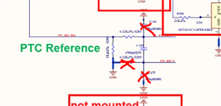
    In your original post you wrote that you are using REF register = 0x0A (both VREF buffers enabled, internal VREF on, internal VREF selected as the source). In your schematic you are showing a "PTC reference" circuit connected to the REFx0 reference input pair. Can you confirm which reference source you are using for the measurements? In either case, the buffer on REFN0 should be disabled, and that pin should be tied directly to ground i.e. you can remove the 3x components I crossed out in the image below

    Also are you measuring a thermistor (PTC) or an RTD (Pt1000)? You keep using the term "PTC1000", so I am not sure which you are measuring but your circuit looks more like an RTD measurement circuit to me. And then the "3-wire" terminology makes more sense

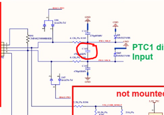
    In the table you provided in the original post, you have a column called "VIN". Those measurements are taken at the ADC pins e.g. the cap I circled below? I also assume this cap is close to the ADC inputs, as it is on the ADS124S08EVM

    You might also try removing the diodes on the inputs to see if there is a leakage current impact from those components

    If you are sampling at 400 SPS, why take one conversion every 1 second? Why not sample slower so you can benefit from lower noise? 

    I would not be concerned about a single measurement having a 20mV error (by single measurement I mean when you measure a 1kohm resistance and a 500uA current source). The ADC internal reference will have a tolerance, as does the IDAC, and if the offset is repeatable it can be removed. Measuring across the input range is more helpful because at least the results you showed initially are randomly "off" at different points from 0 to 2.5V. A constant offset or gain error can be removed, but this is a bit more odd.

    -Bryan