This thread has been locked.

If you have a related question, please click the "Ask a related question" button in the top right corner. The newly created question will be automatically linked to this question.

AFE4490: Design consideration

Part Number: AFE4490


Tool/software:

Hello,

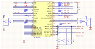
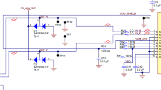
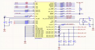
We are using AFE4490RHAT and instead of DB9 connector, we are planning to solder the SPO2 sensor to the board with just 5 Pads on PCB, in that case, how should we route the VCM_SHIELD?

Also what is the impedance control requirement for IN_N and IN_P & TX Pair Signals?

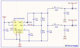
In the development board, there are 2 dedicated power regulators used. Can we use one power regulator?

  • Hello Syed,

    Thank you for your post!

    Please refer to layout guidelines in section 11 of the device data sheet. The goal is to shield as much of the INP and INN input traces as much as possible, whether the signals are coming through a connector or from an on-board module. Below, I've marked where the recommended R-C filter should be placed on the PCB layout. From the RC filter node, you will see two traces routed to the left in parallel with the INP/N traces. They can dead-end once they reach the PD module.

    There is no stringent requirement for impedance control on the TX or RX paths. However, I would strongly suggest to route them as a differential pair and match the impedances of the P and N sides.

    It is possible to use a single power supply, but there could be drawbacks to performance due to the switching currents from the LED drivers. Please refer to section 10 of the data sheet where we describe 3 possible scenarios for configuring the AFE power supplies.

    Regards,

    Ryan

  • Hi, Thanks. Can you also please verify the schematics?

  • Hi Syed,

    • Pin 11 should only have 0.1µF
    • Pin 17-18 (shorted) should have 1µF
    • VCM_AFE should have a 1kΩ||10nF LPF (see layout example in datasheet for placement and shield routing)

    Regards,

    Ryan

  • Hello,

    Thanks for the response. I have changed the decoupling capacitors (PFA images). However, I don't understand point 3. Do I need to connect the 1KAFE4490 DEVKIT SCHEMATICSDecoupling capacitors

  • Hi Syed,

    1kΩ and 10nF are just used to low-pass filter the VCM output. We recommend placing the resistor near the VCM pin, and the capacitor at the opposite end of the shield tracing. You can refer to the layout image I shared earlier.

    Regards,

    Ryan