Because of the holidays, TI E2E™ design support forum responses will be delayed from Dec. 25 through Jan. 2. Thank you for your patience.

ADS1232: Extremely high fail rate of the chip.

Part Number: ADS1232
Other Parts Discussed in Thread: LP2951,

Tool/software:

Dear Team

ADS1232IPWR is being used in one of our customer's product.

the problem is extremely high failure rate of this chip. failure occur while in service.

once the customer returns product to us, we observed that chip is totally dead.

sometimes this chip get destroyed also with the microcontroller on board.

Microcontroller is STM32 type and connected with this chip via SPI interface.

our customer suspects that quality issue of this chip.

please explain how could this happen and what measures can be taken to avoid this happening.

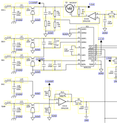
part of the schematic is show below.
  • Hello Thusith,

    The most common cause for a device failure is some sort of over-voltage event.  This can be caused by overshoot/noise on the power supplies, or could be caused by an incorrect voltage applied to the inputs, or even ESD (electro-static discharge).

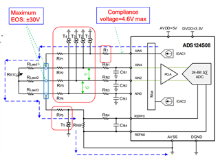
    If the load cell, or other bridge sensor, is connected with short wires to the ADC, then ESD is usually not a concern.  However, if a longer cable is used, then the inputs can be more sensitive to ESD.  You can add 100Ohm series resistors for the analog inputs and reference inputs, which will usually help improve ESD performance.

    Also, I do not see the power supply connections, but I assume AVDD is equal to +5VA and DVDD is equal to +3.3V.  In addition, both AGND and DGND need to be tied together through a low impedance connection, in order to meet the ABS Max ratings in the datasheet.

    Problems can also occur if the inputs (analog or digital) are driven before the ADC power supplies ramp up.  For example, assuming DVDD is connected to the +3.3V supply, and if the STM32 MCU is powered from a different supply voltage, if the STM32 MCU drives the ADC inputs high before the DVDD supply voltage is present, this could also cause damage to the ADC.

    If you could send more of the schematic that shows all of the power connections, including the +5VA and +3.3V regulator circuits, I would be happy to further review and make some additional suggestions.

    Regards,
    Keith Nicholas
    Precision ADC Applications

  • Hello Nicholas

    many Thanks for quick reply!

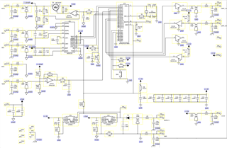
    I have included full schematics here. sorry for low resolution.

    Regards

    Thusith

  • Hello Thusith,

    I do not see anything obvious from the schematics.  Board layout is also important if this is an ESD related failure.  If you could provide an image of the board layout, this may provide some additional clues as to the root cause.

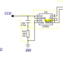
    You also stated that the MCU is also sometimes damaged.  You may want to take a closer look at your 3.3V supply,  Is the correct voltage used?  Have you measured the 5V and 3.3V supplies to confirm the correct voltage levels?  The schematic shows the same symbol as the 5V part, including (5V_TAP) for pin 6.

    Regards,
    Keith

  • Hello Keith

    The schematics lacks some information. IC6 is LP2951-33DR. +5V and +3.3V are correct.

    My concern is also about damage by ESD or incompatibility of interfacing. so we have to convince the customer.

    Do you think existing protections of this board are sufficient?

    what would you suggest for additional protection?

    what kind of factors we should pay attention about end application?

    please advise.

    Regards

    Thusith

  • Hello Thusith,

    I would recommend additional input ESD protection for the board.  However, if ESD is not the root cause of failure, then improving ESD tolerance may not significantly reduce the failure rates.

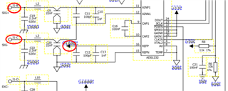
    As a starting point, the easiest improvement is to add 100ohm series resistors to the SIG+, SIG- and the REFP inputs, in the locations shown below:

    Further ESD protection can be added by the addition of external ESD diodes.  Please take a look at the following TI Precision Labs that discusses this in more detail.

    https://www.ti.com/content/dam/videos/external-videos/en-us/9/3816841626001/6303631504001.mp4/subassets/slides-protecting-delta-sigma-input-circuit-operation.pdf

    Other possible causes for high failure rates of device:

    1.  External high voltage source accidentally connected to any of the input connections, such as the Supply+ source for the +5V and +3.3V regulator circuits.

    2.  Are there any production board tests that could accidentally exceed the maximum voltage ratings of the parts?

    3.  Open connections on regulator circuits, causing the supply voltage to exceed the ABS Maximum voltage rating of 6V.  This could be caused by excessive board flexing when making connections to the board, resulting in broken solder joints.

     4. Poor regulation due to very light, low-level, loads on the LP2951 regulators.  These parts are specified for output load currents of 100uA or higher.  If the STM32 MCU and ADS1232 are in low power mode, the load current may be reduced to 1uA or less, which could result in loss of regulation.  This depends on the exact version of the regulator used, but this is a possible concern.  I would recommend adding a small load to each of the regulator outputs.  33kOhm for the 3.3V and 50kOhm for the 5V regulator outputs would ensure a minimum 100uA load on each regulator.

    Regards,
    Keith

  • Hello Keith

    Thanks for the information. I will contact the customer with these information and try to solve

    his problem. If unsuccessful I will contact you later.

    Until then Goodbye!