This thread has been locked.

If you have a related question, please click the "Ask a related question" button in the top right corner. The newly created question will be automatically linked to this question.

ADS1294 Read ECG ?

Other Parts Discussed in Thread: ADS1294

Hi, dear TI staff

I have a problem with ADS1294 to read a correct ECG.

I write/read correct register, and test signal.


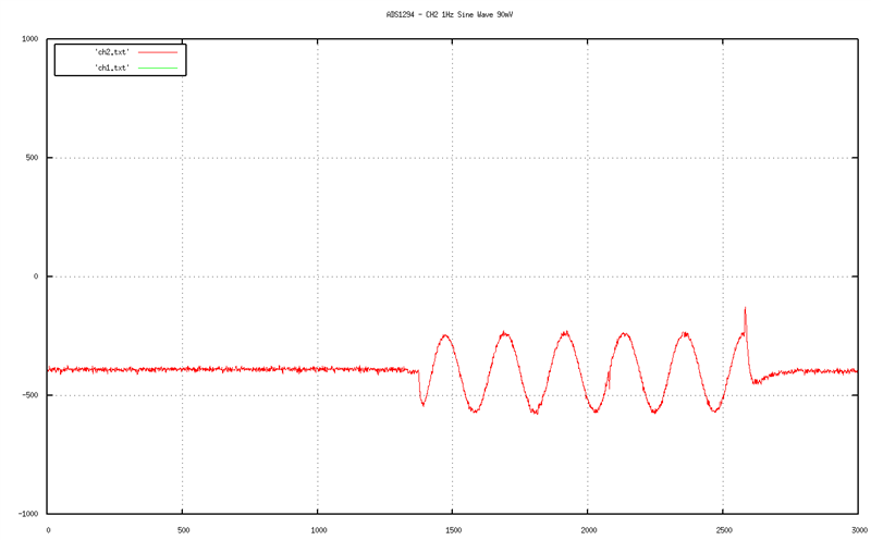
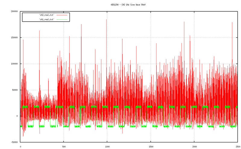
But when try to read Signal i receive this segnal:

This is my part of schematic to use with electrode:


My procedure is

Stop ADS

Reset ADS

Sdatac

Set Config3 0xC0

Set Config1 0x06

Set Config2 0x00

Set Ch1 0x80

Set Ch2 0x00

Set Ch3 0x00

Set Ch4 0x80

Start ADS

Rdatac


What is wrong ???

Please help me.

  • Hi Andrea,

    It's difficult to say what might be wrong with your setup of the ADS1294 with the limited information provided above.  One thing you might start off with is simply hooking  a signal generator with a 2-3hz sine wave on the input to CH2P with a DC input of Vref/2 on CH2N and verify that you can see the sine wave in your display.  You should be able to do the same thing with CH3P. 

  •  

    Dear Tom,


    thanks for the help. 


    We have tested with ha 90mV 1Hz sine wave, connected to the CH2.


    In our configuration CH1 is not used, so as requested by the datasheet it is 

    connected to AVDD.


    We set up CH1 in test mode (0x05) and CH2 in Normal Input (0x00).


    Nothing is connected to RLDINV and on others channels.


    In this image I plotted CH1 and CH2 togheter, and is possible to see how the sine 

    wave signal introduces variations into the Test wave.


    In this image I plotted CH1 and CH2 increasing the focus on samples with 

    amplitude between [-1000:1000]. 


    Is possible to see a good sine wave, even if the test signal became corrupted.


    Leaving the same configuration and doing a real ecg sampling the result is just 

    noise.

    The amplitude of the signal is significantly changed and no ecg signal visible.

    Can you help us?


    Thanks

    Simone Genovese and Andrea Genovese


  • Hi Simone and Andrea,

    Cabling and RLD are usually the reason behind noisy signal like those you are seeing.  Please have a look over this application note and let me know if that helps:

    http://www.ti.com/lit/an/sbaa188/sbaa188.pdf

    There are also some FAQs and additional app note resources under the Design Notes tab which you might find useful.

  • Hi Tom,

    I want to tell you that you were right.

    CMR with RLD worked for us, but not completely.

    I have still a little noise.

    I'm sampling in low power mode, do you think this is the problem?

    Any suggestion?

    Thanks.


    Simone Genovese