Tool/software:
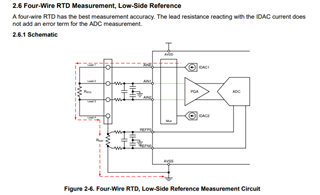
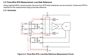
I am using the ADS1120 to measure RTD (Resistance Temperature Detector) values. I am utilizing AIN1 and AIN2 as the input channels and configuring IDAC1 and IDAC2 for excitation current at 1000 μA (1 mA). Additionally, I need the data rate to be set to 600 SPS (Samples Per Second).
I have already configured and verified the SPI communication to read and write registers, but the ADC readings I get are unstable and incorrect, which I believe might be due to improper configuration of the ADS1120 registers.
Here are the key requirements:
- AIN1 and AIN2 should be configured as differential inputs.
- IDAC1 and IDAC2 should output 1000 μA excitation current to the RTD sensor.
- The data rate should be set to 600 SPS.
- Ensure proper configuration of registers for stable operation.
Below is my code snippet for configuring the ADS1120 and reading the ADC values. I suspect an issue in register configuration, and I would appreciate help with debugging this.
#include "stm32f4xx_hal.h" // For STM32 environment
#include <stdint.h>
#define ADS1120_CMD_WREG 0x40 // Write to register command
#define ADS1120_CMD_RREG 0x20 // Read register command
#define ADS1120_CMD_START 0x08 // Start a new conversion
#define ADS1120_CMD_RESET 0x06 // Reset command
#define ADS1120_CS_LOW() HAL_GPIO_WritePin(GPIOA, GPIO_PIN_4, GPIO_PIN_RESET)
#define ADS1120_CS_HIGH() HAL_GPIO_WritePin(GPIOA, GPIO_PIN_4, GPIO_PIN_SET)
// SPI handle (configured earlier)
extern SPI_HandleTypeDef hspi3;
// ADS1120 Register Addresses
#define CONFIG_REG_0 0x00
#define CONFIG_REG_1 0x01
#define CONFIG_REG_2 0x02
#define CONFIG_REG_3 0x03
// Function Prototypes
void ADS1120_Reset(void);
void ADS1120_Config(void);
uint16_t ADS1120_ReadData(void);
void ADS1120_WriteRegister(uint8_t reg, uint8_t value);
uint8_t ADS1120_ReadRegister(uint8_t reg);
// ADS1120 Reset Function
void ADS1120_Reset(void) {
ADS1120_CS_LOW();
HAL_SPI_Transmit(&hspi3, (uint8_t[]){ADS1120_CMD_RESET}, 1, HAL_MAX_DELAY);
HAL_Delay(2); // Wait for ADS1120 reset completion
ADS1120_CS_HIGH();
}
// ADS1120 Configuration Function
void ADS1120_Config(void) {
// Configuration Register 0 (MUX, PGA, and Data Rate)
// MUX: AIN1-AIN2 (differential), PGA = 1, Data Rate = 600 SPS
uint8_t config0 = 0b00110010; // MUX[3:0]=0011, PGA=1x, DR=600 SPS
// Configuration Register 1 (Mode, Conversion Mode, and Temperature Sensor)
// Mode = Normal, Conversion Mode = Continuous, IDAC enabled
uint8_t config1 = 0b00000010; // MODE=Normal, CM=Continuous, TS=off, IDAC=Enabled
// Configuration Register 2 (IDAC Current)
// IDAC1 and IDAC2 set to 1000 μA
uint8_t config2 = 0b00001100; // IDAC1 and IDAC2 = 1000 μA
// Configuration Register 3 (IDAC Routing)
// Route IDAC1 to AIN1 and IDAC2 to AIN2
uint8_t config3 = 0b00011011; // I1DIR=AIN1, I2DIR=AIN2
// Write to ADS1120 registers
ADS1120_WriteRegister(CONFIG_REG_0, config0);
ADS1120_WriteRegister(CONFIG_REG_1, config1);
ADS1120_WriteRegister(CONFIG_REG_2, config2);
ADS1120_WriteRegister(CONFIG_REG_3, config3);
}
// Function to Write a Register
void ADS1120_WriteRegister(uint8_t reg, uint8_t value) {
uint8_t command = ADS1120_CMD_WREG | (reg & 0x03); // Write command with register address
ADS1120_CS_LOW();
HAL_SPI_Transmit(&hspi3, &command, 1, HAL_MAX_DELAY);
HAL_SPI_Transmit(&hspi3, &value, 1, HAL_MAX_DELAY);
ADS1120_CS_HIGH();
}
// Function to Read Data from ADC
uint16_t ADS1120_ReadData(void) {
uint8_t command = ADS1120_CMD_START; // Send START command
uint8_t data[2] = {0};
uint16_t adcResult = 0;
ADS1120_CS_LOW();
HAL_SPI_Transmit(&hspi3, &command, 1, HAL_MAX_DELAY);
HAL_SPI_Receive(&hspi3, data, 2, HAL_MAX_DELAY);
ADS1120_CS_HIGH();
// Combine MSB and LSB
adcResult = ((uint16_t)data[0] << 8) | data[1];
return adcResult;
}
int main(void) {
HAL_Init(); // Initialize HAL
// Configure peripherals, clocks, SPI, and GPIO here
ADS1120_Reset(); // Reset ADS1120
ADS1120_Config(); // Configure ADS1120
while (1) {
uint16_t adcValue = ADS1120_ReadData();
printf("ADC Value: %u\n", adcValue);
HAL_Delay(100); // Adjust delay as needed
}
}
static void MX_SPI3_Init(void)
{
/* USER CODE BEGIN SPI3_Init 0 */
/* USER CODE END SPI3_Init 0 */
/* USER CODE BEGIN SPI3_Init 1 */
/* USER CODE END SPI3_Init 1 */
/* SPI3 parameter configuration*/
hspi3.Instance = SPI3;
hspi3.Init.Mode = SPI_MODE_MASTER;
hspi3.Init.Direction = SPI_DIRECTION_2LINES;
hspi3.Init.DataSize = SPI_DATASIZE_16BIT;
hspi3.Init.CLKPolarity = SPI_POLARITY_LOW;
hspi3.Init.CLKPhase = SPI_PHASE_1EDGE;
hspi3.Init.NSS = SPI_NSS_SOFT;
hspi3.Init.BaudRatePrescaler = SPI_BAUDRATEPRESCALER_8;
hspi3.Init.FirstBit = SPI_FIRSTBIT_MSB;
hspi3.Init.TIMode = SPI_TIMODE_DISABLE;
hspi3.Init.CRCCalculation = SPI_CRCCALCULATION_DISABLE;
hspi3.Init.CRCPolynomial = 10;
if (HAL_SPI_Init(&hspi3) != HAL_OK)
{
Error_Handler();
}
/* USER CODE BEGIN SPI3_Init 2 */
/* USER CODE END SPI3_Init 2 */
}


