This thread has been locked.

If you have a related question, please click the "Ask a related question" button in the top right corner. The newly created question will be automatically linked to this question.

ADS4225: ADC input scheme

Part Number: ADS4225

Tool/software:

Hi TI supporter,


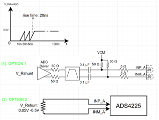
I have some question regarding to ADC input.

With OPTION1
: I catch the Option 1 in page 81 of https://www.ti.com/lit/ds/symlink/ads4225.pdf?ts=1735896348156&ref_url=https%253A%252F%252Fwww.ti.com%252Fproduct%252FADS4225 . 
As I understand, the purpose of VCM termination is prevent the glitch when sampling switched internal ADS4225 and the x2 0.1uF cap is DC block.
It means that if I read the voltage in above waveform at 100ms, the (INP_A-INM_A) will be 0V. It mean this option1 not use for reading the constant DC ?

With OPTION2: 
I have some concern:
1. Does OPTION2 scheme will work ?
2. If we installed the VCM termination as option1, the VCM might leak via 50R then via Rshunt. If not, how to prevent the glitch when sampling switched internal ADS4225. Please give your advice!
3. The ADC range is 2V, but the input only 0.5V. Do you have any recommend for multiple the V_Rshunt (ex: differential buffer amplifier,..)

Best Regards,
Long Le Nguyen
 

  • Hi Long,

    I don't understand what Option 2 is doing. Please describe more.

    What is your ultimate goal for using the ADC4225?

    Do you need to AC couple or DC couple your signal to the ADC?

    Option 1 shows an AC coupled configuration using an amplifier, therefore, the reason for the two resistors connected to the analog inputs of the ADC are for setting the common mode voltage (VCM). The ADS4225 is an unbuffered ADC, so its needs a VCM provided externally to the analog inputs.

    If you remove the DC blocking caps from option 1 above, then this would DC couple the amp to the ADC. And the VCM pin from the ADC would need to connect to the VOCM pin of the amplifier. This will drive the VCM of the ADCs analog inputs.

    Regards,

    Rob

  • Hi Rob,

    Thank for your comments.
    More details for my question:
    I have the current sink circuit as below, I want to read the V_Rset value by using the ADS4225 ( parallel CMOS).
    The voltage range of V_Rset is 0V -0.5V as waveform below.
    Please advice the connection from Rset to ADC input.


    Thank you,
    Long Le Nguyen

  • Hi Long,

    I would implement the circuit interface something like this. See below.

    Regards,

    Rob

    https://www.ti.com/tool/DIFFAMPGAINCALC