ADS131E06:Bits of data read are inverted.

Part Number: ADS131E06

Tool/software:

We have made a board with a new ADS131E06 for our sensor.
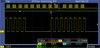
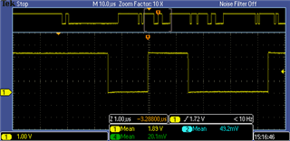
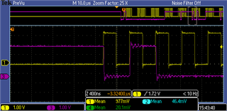
The ADS131E06's read data bits flip once every tens of thousands of times.
The point of inversion is not the same every time, neither in the channel nor in the bit.

The sensor has several types of external communication,
This phenomenon has not been observed with USB communication or RS422,
Only UDP and TCP in Ethernet communication show the symptom.

Also, TCP flips bits more frequently than UDP,
communication is definitely affected, though,
However, it is not clear whether the cause of the data corruption is
 Is it happening during SPI communication?
 Is it caused by a conversion in the ADS131E06?

Cannot be identified.
Any advice would be appreciated.

What we tried:
・Change of SCLK cycle 1M to 4MHz
Change of pull-up resistor value of SDO 1k to 4.7k Ohm
Add damping resistors to SCLK, SDI and SDO 33 Ohm
Short-circuit between IN*P and IN*N (*:1-6)
Change of cycle for performing AÐ conversion 0.5 ms, 1 ms
Change of communication interval 1 ms, 2 ms
Change of SPI read timing
Change of the common mode filter for Ethernet communication.

ADS131E06 settings:
 ・AVDD=4.5V, DVDD=3.3V
 ・Recommended minimum value for capacitors.
 ・Register.
  0x01: 0xb2 DAISY_IN=0, CLK_EN=1, DR=0b010 (24bit 16k)
  0x02: 0xe0, INT_TEST=0,TEST_AMP0=0,TEST_FREQ=0
  0x03: 0xe0, PDB_REFBUF=1, VREF_4V=1, OPAMP_REF=0, PDB_OPAMP=0
  0x04: 0x00, COMP_TH=0

  • Hi KEIZO MIZUI,

    You have a duplicate post, I have closed one of your posts.

    ADS131E06 ADC can not detect and know which interface (USB, RS422 or Ethernet) you use and then shift out the data differently. In order to verify the ADC's conversion and communication, you can short the input by setting MUXn[2:0] to 001b CHnSET registers or use a precision DC signal, then keep monitoring the ADC SPI timing especially when flipping bits TCP is observed. The following timing is a typical timing:  

    By the way, your 1Mhz SCLK frequency is not enough to read all channel data, the sample period is 1/16k=62.5us, you will have to read STATUS word+all data during this time.

    BR,

    Dale

  • HI Dale

    Thanks for the reply.

    The conversion does not use continuous mode,
    After the start command is sent,
    The stop command is sent immediately after the start command is sent.
    The datasheet states that the settling time is 584tclk when DR=0b101 and tclkmax=588ns, so
    Max 584*588ns=344us
    Conversion is done once every 500us.

    The following is a simplified of the process in the microcontroller.

    Initialize();
    while(1){
     if(timecount > 500us){
      SPI_DSAD_READ();
      SPI_DSAD_Conversion_START();
      SPI_DSAD_Conversion_STOP();
      calculation_for_sensor();
     }
     communication_process_read();
     if(flg_send_data){
      communication_process_write();
     }

     timecount++;
    }

    About once every tens of thousands to hundreds of thousands of times when the communication is an Ethernet communication.
    spikes occur.

    Measured value:

    DEC
    CH1 CH2 CH3 CH4 CH5 CH6
    -8250 -9750 -8200 -9500 -7100 -9270
    -8190 -9760 -8260 -9410 -7120 -9420
    -8268 -50900 -8208 -9506 -3532 -531506 <= spike data on CH2,CH6
    -8340 -9870 -8140 -9430 -7240 -9210
    -8300 -9850 -8080 -9270 -7260 -9300


    HEX
    CH1 CH2 CH3 CH4 CH5 CH6
    FFDFC6 FFD9EA FFDFF8 FFDAE4 FFE444 FFDBCA
    FFE002 FFD9E0 FFDFBC FFDB3E FFE430 FFDB34
    FFDFB4 FF392C FFDFF0 FFDADE FFF234 F7E3CE
    FFDF6C FFD972 FFE034 FFDB2A FFE3B8 FFDC06
    FFDF94 FFD986 FFE070 FFDBCA FFE3A4 FFDBAC


    CH2 FFD*** -> FF3*** D(1101)->3(0011)
    CH6 FFD*** -> F7E*** F(1111)->7(0111)


    No symptoms of bit inversion are observed when using USB or RS422.

    It is certain that the spikes are caused by Ethernet communication, but
    It is not known whether it is due to noise or a software problem.
    Could the ADS131E06 be causing the bit flipping described above?
    I would like to get advice if there are effective measures that can be taken to counteract the problem.

    Best regards,

    Keizo Mizui

  • Hi KEIZO MIZUI,

    I will check the details and get back to you soon.

    BR,

    Dale

  • Hi KEIZO MIZUI,

    As I explained in my previous post, ADS131E06 ADC can not detect and know which interface (USB, RS422 or Ethernet) you use and then shift out the data differently, definitely the bit flipping is not caused by the ADC. I also already suggested you to keep monitoring the ADC SPI timing especially when flipping bits TCP is observed so that you can verify and double check it.

    BR,

    Dale

  • Hi Dale

    We are still testing.
    I have seen improvement by modifying the command to send.

    Even though I am using it in continuous mode.
    I had been sending RDATA commands.
    I was checking the datasheet and noticed that RDATA was not needed, so I corrected it,
    This is the result of about half a day of checking, but no spikes have occurred.
        The command that was causing spikes {0x12, 0x08, 0x0A, 0x00, 0x00, ... 0x00, 0x00}
        Commands after correction                    {0x08, 0x0A, 0x00, 0x00, ... 0x00, 0x00}
    What happens if RDATA is sent during continuous mode?

    Also, even if you send an SDATAC to stop the continuous mode and then send an RDATA command to read.
    spikes occurred as well.
    From these facts, it is thought that the spikes are caused by the transmission of RDATA.
    I have no idea how it is related to Ethernet communication, but I am not going to pursue that point in depth.

    I will continue testing for a while longer.

    if there are no problems,
    I will close this case.

    Best regards,

    Keizo Mizui

  • Hi Keizo Mizui,

    The continuous mode places the conversion data in the output register with every DRDY falling edge so that the data can be shifted out directly with the following SCLKs. The RDATA command loads the output shift register with the latest data as well. Hence, the RDATA command does not change anything.

    I would strongly suggest you to monitor the SPI timing and data.

    Regards,

    Dale

  • Hi Dale,

    I only have an oscilloscope.
    It is difficult to extract the waveforms during anomalies.

    (I will think about whether there is any way to do this.)

    As far as the waveform is concerned on an oscilloscope,
    The waveform is clean with no sign of superimposed communication noise.

    It is also unlikely to generate intense pulse noise as it is in an office.

    SCLK

    SDO

    timing  (Ringing is caused by the long GND of the probe.)

    Best regards,

    Keizo Mizui

  • Hi Dale,

    By  a trigger signal from the GPIO pin when the value captured to the microcontroller is abnormal.
    The waveforms could be taken when data corruption is occurring.

    As a result, the phenomenon of data being corrupted when RDATA commands are sent is
    confirmed to occur at the point of transmission from the ADS131E.

    From waveform From Ethernet 
     AD conversion at 0.5 ms intervals.  Sampling at 1 ms intervals  
    channel binary decimal time decimal
    1 111111111101011110011110 -10338 253.6 -10338
    111111111101001101100100 -11420    
    111111111101001111011100 -11300 253.601 -11300
           
    2 111110101111100101001000 -329400 253.6 -329400
    111111111101100001111000 -10120    
    111111111101100001101110 -10130 253.601 -10130
           
    3 111111111111110110011000 -616 253.6 -616
    111111111111001110111100 -3140    
    111111111111010010011000 -2920 253.601 -2920
           
    4 111111111111101101011100 -1188 253.6 -1188
    111111111101001100001010 -11510    
    111111111101001100010100 -11500 253.601 -11500
           
    5 111111010000000000110010 -196558 253.6 -196558
    111111111100111001100100 -12700    
    111111111100111001100100 -12700 253.601 -12700
           
    6 111111111111010011000000 -2880 253.6 -2880
    111111111110010110001110 -6770    
    111111111110010111111100 -6660 253.601 -6660

    For the moment, we are continuing the test with no RDATA being sent, but
    Spike data has not yet occurred.

    I forgot to mention that when DR = 0b11 (8kHz) at 1kHz AD conversion
    spikes did not occur even when RDATA was being transmitted.

    Best regards,

    Keizo Mizui

  • Hi Keizo Mizui,

    Regarding your description, this phenomenon only happened with UDP and TCP in Ethernet communication mode and it was not observed with USB communication or RS422 when the RDATA commands were sent to the ADC. Please correct me if my understanding is incorrect.

    You should have a microcontroller between those interface and the ADC, ADS131E06 ADC does not directly use any Ethernet or USB communication or RS422 interface, it only uses SPI bus, so it is hard for me to understand how the phenomenon is related to those interface, but this is definitely not caused by the ADC. If you only saw the phenomenon at higher data rate and also it is also related to those interface, you may have to check the difference between those interfaces in terms of hardware or software, especially your PCB layout that could lead to crosstalk to the interfaces including the SPI bus on your circuit board.

    BR,

    Dale

  • Hi Dale,

    When Ethernet communication is not performed
    The trigger for detecting data corruption is not engaged.
    Noise originating from the communication is definitely having an effect.

    As far as the board pattern is concerned.
    I can't find any parts that might be the cause of the problem.

    Considering that any channel data can be turned into data in simultaneous scans.
    Where is it most likely that noise is interfering with the terminals?

    Best regards,

    Keizo Mizui

  • Hi Dale.

    Thank you for your help.

    To check whether the RDATA command is one of the causes of the data corruption
    I replaced RDATA with commands that did not seem to affect the operation (WAKEUP and RDATAC) and invalid values (0xff).When any of the commands were sent, the readings were not always normal and did not validate. Instead of sending RDATA, a delay time was set and the timing was changed, but no data corruption occurred.

    After modifications were made to avoid transmitting RDATA,
    received data for several days, but no spikes occurred.
    The case is considered resolved and closed.

    Best regards,

    Keizo Mizui