This thread has been locked.

If you have a related question, please click the "Ask a related question" button in the top right corner. The newly created question will be automatically linked to this question.

ADS8689: help regarding flexible AFE 0-10V/4-20mA

Part Number: ADS8689
Other Parts Discussed in Thread: TIDA-01333, OPA192

Tool/software:

Hi TI team,

I have a question regarding the ADS8689:

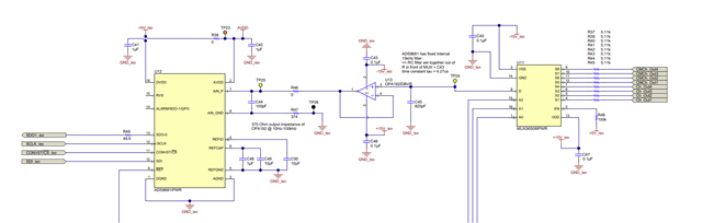
First of all, I would like to ask if I can optimise this circuit. It is similar to the circuit shown in SBAA51. And is supposed to measure 0-10V voltage signals or 4-20mA current signals. Both supplied by 3-wire sensors with a signal wire, a GND wire and a 24V supply wire. So I only need to measure single ended signals and I am not sure if I can optimise this circuit further, in particular if I need the instrumental gain amplifier for CMRR if I only measure single ended signals. And whether it is necessary to mux the AINN signal if it is just connected to GND.

My second question is regarding the filtering of the inputs, because the cut-off frequencies of the sensors are at 1khz-3db, so I think I should be fine if the internal cut-off frequency of the ADC lpf is 15khz, if the signal with the highest frequency that I want to measure is 1khz. I am just unsure how the mux interferes with this and how I should design the filter before the mux so as not to interfere with the internal ADC lpf. Any help would be greatly appreciated. 


  • Hi Jonas,

    Sorry this one was missed - give us time to look over your queries and go through the SBAA551 application note.  We'll get back to you ASAP.

  • Hi Jonas,

    the INA was added for CM rejection and to buffer the sensor signal for the ADC to increase update rate. If you have only single-ended signals you may switch to a standard op-amp. Whether you need an op-amp is dependent on your system parameter, such as sensor our impedance and update rate.

    It is good practice to limit the bandwidth of the signal as needed. This can be done with a simple 1st order LPF if sufficient. As you add a cap in front of the ADC input anyway (charge reservoir to the ADC) it comes "for free", together with a series resistor. If an op-amp is required you mal also use it to form a LPF.

    Hope this helps!

    Best regards,
    Lars

  • Hi Lars, thank you for your detailed reply, I found this reference design TIDA-01333 (www.ti.com/.../TIDA-01333 ) which I think should be more suitable for my application. I just have 2 questions:
    Firstly, is it possible to implement the open wire detection using only a 2Mohm resistor pulled up to 13V before the MUX?
    And secondly, I am not quite sure how the C44 100pF capacitor were chosen, as it was not mentioned in the design guide.
    Best regards,
    Jonas

  • Hi Jonas,

    Unfortunately the author of TIDA-01333 has left the company.  Using a high value pullup to detect open wire is fine.  For C44, compare the schematic to the text - C43 is the bypass cap on the OPA192.  I believe that note is actually referring to C44, not C43.