This thread has been locked.

If you have a related question, please click the "Ask a related question" button in the top right corner. The newly created question will be automatically linked to this question.

ADS7138-Q1: Reading analog inputs

Part Number: ADS7138-Q1
Other Parts Discussed in Thread: ADS7138, BP-ADS7128

Tool/software:

Hey Team,

We are working on a design using ADS7138QRTERQ1. We have been trying to read the analog inputs, however it always returns ‘00’.

We can communicate to the device successfully by reading the system status register ’00’ which returns default ‘81’.

Our design has on AN0 input to monitor a ~2.7VDC voltage and another just with voltage level inputs, as well as NTCs. However, we have been just attempting to ready a voltage input.

The controller is set to manual mode to read ADC channel ‘0’ and read register address 0x60 MAX_CH0_LSB.

As such:

  • Set to ADC channel ‘0’:
  • I2c w 4 14 081100
  • Read MAX_CH0_LSB:
  • I2c w 4 14 1060
  • I2c r 4 14 1

Returns:

  • 00

We tried MAX_CHx_LSB/MSB, MIN, RECENT.

LSB/MSB both MAX and RECENT returns ‘00’

MIN LSB/MSB returns ‘FF’

We verified voltage is at the pin of the analog input pins.

We also tried resetting ‘brown out’ by writing ‘81’ to address ‘00’.


We have been attempting to read any value other than ’00’ with no success. Is there a configuration setting we are missing that is needed before the ADC can start reading?

Do you have any questions, or suggestions which the team could use to move forward?

  • Hi Dajon,

    The STATS_EN bit in the GENERAL_CFG register needs to be set to high before the MAX, MIN, and RECENT registers begin to update. They should be getting correct data after doing so. Let me know if they need any further help in this.

    Regards,
    Joel

  • Hi Joel,

    I set STATS_EN in GENERAL_CFG register to 1, but reading MAX or RECENT still returns '00'.

    I performed sequence as:

    i2c w 4 14 080120

    i2c w 4 14 10a2

    i2c r 4 14 1

    00

    Is conversion required to be setup for any reading? I have not reconfigured the conversion, currently mainly trying to get any output values other than '00' to show, that way I know I am reading an analog input.

    Any other configurations I need to configure?

    Thanks!

    Titngai

  • Hi Titngai,

    Yes, a conversion has to be initiated before the registers are updated with values. In manual and auto-sequence mode, conversion control begins with the 9th falling edge of SCL. See section 8.4.2 of the datasheet for information on how to begin conversion with the device.

    Could you help in explaining what you would expect from the device in this line?

    i2c r 4 14 1

    Regards,
    Joel

  • Hi Joel,

    i2c r 4 14 1 line is second half after i2c w 4 14 10a2, as described in datasheet for a single read (8.5.1.1).

    i2c w 4 14 10a2

    i2c r 4 14 1

    It means to read 1 byte from a2 register.

    I am expecting to get 1 byte from channel 1 RECENT register with stored previous Channel 1 (AN1) analog input data. Our analog input 1 (AN1) is simply a 1.65V volage input.

    We are attempting 'autonomous mode' in section 8.4.4, which should just start conversion without a start, but currently getting a different result, which did not return any value.

    Could you share a sample i2c sequence to read an analog input in manual mode or autonomous mode? For example, 3.3V reference input and analog inputs of 2V.

    Thanks,

    Titngai

  • Hi Titngai,

    Do you have a logic analyzer that is able to export captures as a file? It would be best for me in determining that the lines you are writing with your utility are actually executing what you are expecting it to execute.

    I will work on a sample I2C sequence for you.

    Regards,
    Joel 

  • Hi Joel,

    Good info. We have a Total Phase Beagle. I'll try capture the communications.

    Thanks,

    Titngai

  • Hi Titngai,

    Below, the device is configured for manual mode conversion.

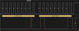
    In this picture, I've initiated conversion readout with the ADS7138. 

    In the first frame, the controller sets up a read to the ADS7138 (7-bit I2C address 0x10), and the device acknowledges. The next 4 frames are 2 data conversions, as each conversion is encoded across 2 I2C frames. The controller acknowledges each of the frames from the device. 

    When the controller wishes to stop the conversion process, it provides a NACK to the device, as shown below. Afterwards the device will stop providing conversion data.

     '

    Does this help visualize what you should be expecting when you start and end data collection?

    Regards,
    Joel 

  • Hi Joel,

    Can you please send us what you typed in to 'initiate conversion readout"  I'm trying to see if we are making some of error in the way we are typing in our commands.  Thank you!

  • Hi Christopher,

    This was taken with the BP-ADS7128 evaluation module, and that source code is not available to share publicly. I'm not familiar with the I2C utility that you're using, so I can't say for certain what it translates to. 

    Perhaps you can try to recreate these same captures with your control program? If it does not yield the same result, please share the command that you typed in, and a logic capture or oscilloscope capture of the resulting I2C waveform. I should be able to determine how the control program works given a couple examples.

    Regards,
    Joel