This thread has been locked.

If you have a related question, please click the "Ask a related question" button in the top right corner. The newly created question will be automatically linked to this question.

ADS7865: Bypass capacitor value on BVDD

Part Number: ADS7865

Tool/software:

Hello,

My customer has a question for ADS7865.

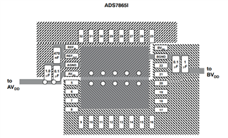
The dadasheet says that 0.1uF and 10uF should be placed for BVDD on P25 like the below.

On the other hand, "TERMINAL FUNCTIONS" on P7 recommends to use 1uF and Figure 36 on P24 also uses 1uF.

Also the the below from left side of P25 and it recommends 1uF~10uF.
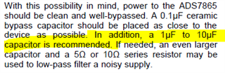
Their question is what capacitor value they should use for BVDD, 1uF? 10uF or any between 1uF-10uF?

Regards
Oba

  • Hello Oba, 

    Welcome to the E2E forum! 

    Typically we recommend to add decoupling/bypass capacitors between the supply and ground to stabilize (reduce spikes and/or dips) and reduce any noise injection from the supplies to the devices.

    A 0.1uF is usually able to filter out most of the noise, and additional larger capacitors usually ranging from 1uF to 10uF help more with the stabilizing to supply level and currents. When it comes to actual placement (layout), in the path from the device supply pin (BVDD) to the supply source the capacitor order should be by increasing size order (smallest closest to device and largest to supply source). The 0.1uF should be as close as possible to the device to ensure that any possible noise it could acquire in the path from the supply to the device is filtered. In the increasing size of capacitors are used to keep a charged resource that would help with any spike or dip occasions. 

    These are usually good schematic/layout best practices to follow and usually apply to most devices, but depending on the device and/or system it might require more or less filtering and stability. Noise and power consumption are usual reasons to add more capacitors in either range, but having at least a 0.1uF for filtering and a 1uF or 10uF capacitor for stability is usually sufficient. 

    For the ADS7865 they do recommend to have at least a 1uF capacitor to decouple the supply, for stability (page 7). In order to also implement some filtering it is also recommended to add a 0.1uF capacitor close to the device (Page 25, Supply section).  The left side of page 25 is referring to all device power pins in general (BVDD and AVDD), where it recommends having a 0.1uF and either a 1uF or 10uF capacitor. 

    Please follow the layout recommendations on page 26 of the datasheet and add at least a 0.1uF and a 1uF capacitor to both BVDD and AVDD. if desired or if the supplies are shared with more devices adding larger capacitors closer to the source could help too. 

    Best regards, 

    Yolanda

  • Hello Yolanda,

    Thank you very much for your very detail answer.

    Regards,
    Satoshi Obata