This thread has been locked.

If you have a related question, please click the "Ask a related question" button in the top right corner. The newly created question will be automatically linked to this question.

ADS1292: Thermal PAD of ads1292: where to connect?

Part Number: ADS1292


Tool/software:

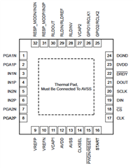
Hi! I am using the ADS1292 in my PCB and I connected the Thermal pad to the GND. I am using bipolar power supply, so the AVDD and AVSS are +2.5 V and -2.5 V, respectively. Is there a problem in connecting the thermal pad underneath the IC to ground 0V ? The chip is not ansering my SPI commands, I wonder if that´s why.

Best,
Pedro.

  • Pedro,

    See page 4 of the datasheet: "Thermal Pad, Must be connected to AVSS". It's very likely this is causing your issue, as your AVSS is -2.5V. If you switch to a unipolar supply and set AVSS to 0V, then you can check if communication works before you rework your board.

    Hope this helps!

    Regards,

    Shane

  • Hi! Thanks for the answer.

    I tried what you suggested and still nothing. I am trying to test by looking at the DRDY pin to see if it toggles as expected after initialization. 
    Here is my circuit:


    I've already connected the thermal pad (pin EXP number 333) to -AVSS in the presented schematics. 
    Any ideas if there is any wrong connections ?

    Notes:

    Bipolar configuration
    -AVDD = -2.5V
    +AVDD = +2.5V
    DVDD = 3v3


    Thanks,
    Pedro.

  • Pedro,

    Can you tell me what your SPI settings are and the order of commands being sent? Keep in mind the ADS1292 samples the SPI data line on the clock line's falling edge, and also requires the SDATAC command to be sent prior to register reads or writes.

    If possible, can you send a screenshot of an oscope or logic analyzer showing the MOSI, SCK, MISO, and DRDY lines during initialization.

    Shane

  • Hi!

    The SPI settings are (configured in stm32 cube ide):

    Baudrate: 12 Mbits/s
    Clock polarity: Low
    Clock Phase: 2nd Edge.
    Data Size: 8 bits.

    I dont have access to an osciloscope right now, but will do this test soon.

    Thanks

  • Also, I am sending SDATAC command first, as explained in the datasheet

  • Update:

    The ads1292 appears to be alive...as soon as I initiate the device, the DRDY pin toggles at 500 Hz, in 2ms intervals, as it should accordingly to the datasheet... The problem now seems to be the SDATAC sending... The only thing I have to do is send the value 0x11 (SDATAC) right? and the DRDY interrupt should stop.

  • Pedro,

    Regardless of SDATAC or RDATAC mode, DRDY will assert on a conversion completion. DRDY can toggle while you read/write to the registers. Before you can write to the registers, you must issue SDATAC (SPI_WRITE(0x11)) to switch to that mode. You can leave it operating in this mode and read samples.

    While in SDATAC, you must issue a SPI_WRITE(RDATA), followed by a SPI_READ() each time you want to read a sample.

    Shane

  • I see. I am also trying to read the ID from the ADS1292 ID register, to verify that the SPI is working properly. 
    I am sending the following message:

    SPI.WRITE(0b00100000)
    SPI.WRITE(0b00000000)
    SPI.READ() -- read one byte for the ID value.

    Is this correct? Still not bing able to read the expected ID, which is, I believe: 0b01010001 (0x51). 

    Pedro.

  • Pedro,

    When you follow the above sequence, what byte do you get on the SPI.READ?

    Shane