This thread has been locked.
If you have a related question, please click the "Ask a related question" button in the top right corner. The newly created question will be automatically linked to this question.
Tool/software:
Hello TI team,
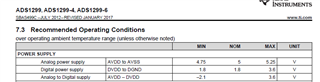
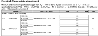
I have designed a medical device that use ADS1299 in the continuous reading mode. According to the datasheet, the power consumption should be 8.14mA including I_AVDD and I_DVDD @ 3.3V.
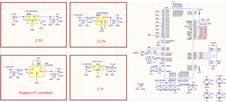
In my design, the main power comes from a 3.7V battery (V_SWITCH), and I've used four regulators to get 3.3V, +2.5V, -3.7V, and -2.5V. However, the actual power consumption is quite different from what's mentioned in the datasheet. The current from the V_SWITCH line is about 15mA, and I've measured the output current of each regulator as follows:
Reg3.3V = 1.1mA
Reg+2.5V = 7.29mA
Reg-2.5V = 7.25mA
Could you please take a look at my schematic and help me figure out why there's such a big difference in power consumption?
Thanks a lot for your help!
Saeed
Hi Saeed,
Thank you for your post.
Are you measuring AVDD and AVSS current in the same direction with respect to the ADS1299? I would expect the supply current to be equal and opposite polarity for AVSS.
Regards,
Ryan
Hi Ryan,
More investigation has been done. The figure below shows all the measurements:
It seems that data sheet is correct about the current (7.14mA for I_AVDD when AVDD-AVSS=5). But this is just for the ADS. We also repeat the test with single power supply (AVDD=5v, AVSS=0 GND) and the total current was about 8mA from the battery.
In the bipolar supply operation, the issue is that we need to consume another 7 mA to make a -2.5v voltage level that sink 7mA of current. But, what we were expected is that the total power from the battery shows 8mA. Maybe I am wrong. Do you have any Idea/recommendation/suggestion?
Thanks,
Saeed
Hi Saeed,
There should be some quiescent power consumed by the voltage inverter, but I'm not sure if you should expect an additional 7.3 mA. I can try to check this on our EVM and see if the result is similar.
We would be interested in learning more about the product you are working on. I'll send you an email offline.
Regards,
Ryan
Hi Saeed,
Just a quick update:
I was able to measure the supply current on our EVM and the results are fairly consistent with what you have observed. It looks like the current for the negative voltage rail directly adds to the total current required by the initial supply source.
Unipolar operation (AVDD = 5V, AVSS = GND):
Bipolar operation (AVDD = 2.5V, AVSS = -2.5V):
Regards,
Ryan
Hi Ryan,
Thank you for your response. It is a bit disappointing for our design that due to the bipolar operation, we end up using twice the power because of the voltage inverter. I think technically we do not have any other option for the negative power line design.
Now, our only choice to reduce power consumption is to use the unipolar operation. We have already tested this method with AVDD at 2.5V, and the signal looks acceptable. However, according to the datasheet, the AVDD-AVSS should be in the range of 4.75-5.25V
Then, my first question is whether operating the ADS1299 with AVDD at 2.5V (or 3.3V) would cause any issues or unexpected results. Secondly, if we use the unipolar operation, the Vref will be about 1.25V, and the reference voltage on the body will have the same voltage level. Do you think this will pose any issues in terms of safety and IEC 60601-1 compliance?
I would be more than happy to continue this conversation offline.
Thanks,
Saeed
Hi Saeed,
We cannot guarantee proper operation or performance of the ADS1299 outside of the recommended operating conditions.
I will reach out to you via email, and we can continue the conversation there.
Regards,
Ryan