Tool/software:
Hi,
I am currently using the ADS52J65 Evaluation Board (EVM) in combination with the TSW14J50 platform to successfully capture data from the ADC on an FPGA. This setup works as expected.
Now, I have designed a custom PCB that includes only a single ADS52J65 ADC. On this custom PCB, I am also using an LMK04821 PLL Clock Generator to generate the required clock signals. I have verified that the clocks are successfully generated and can be seen coming out of the LMK.
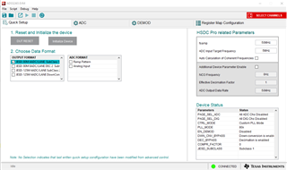
However, when I attempt to configure my custom board and start a data capture, I encounter a timeout error (as shown in the attached image).
I suspect the issue lies in the synchronization between the FPGA and the ADC. Specifically, I believe the FPGA is not achieving sync because the current configuration expects data from two ADCs, whereas my setup includes only one ADC.
Additionally, the following is the pin configuration of my custom board:
I want to configure the TSW14J50 platform to work with this setup, using either 4 lanes or 2 lanes for data capture from the single ADS52J65 ADC.
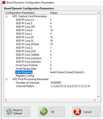
Reconfiguration of TSW14J50:
Configuration Files:
.ini
file for the FPGA to ensure it matches the ADC configuration (e.g., setting lane assignments)?My main goal is to confirm whether the TSW14J50 can operate with only one ADS52J65 ADC and, if so, to understand how to configure both the FPGA and the ADC for this scenario.
Thank you in advance for your support and any documentation or instructions you can provide to assist with this setup.
Best regards,
Alexander Schulz
Hi,
There are multiple interaction between ADS52J65EVM and HSDC_PRO . So without connecting ADS52J65EVM it is difficult to control the setting in HSDC_PRO.
Can you able to do the following ?
1) Connect the ADS52J65EVM to system using USB
2) Connect your custom board to TSW14J50 for capture
3) Whatever device setting needs to be done , you need to do it in both ADS52J65EVM and your custom board .
Please confirm whether this is possible from your end. After this I will check how to manage 2 device to 1 device .
Hi,
Thank you for your response and suggestions.
I use a USB-to-SPI converter on my custom PCB, and the ADS52J65 software seems to recognize it. I have verified the SPI signals and compared them to the ADS52J65EVM. While I haven’t checked every byte in detail, the signals look similar, and based on my understanding, the SPI communication is primarily used to write the registers of the ADS52J65 and the LMK04821.
Additionally, the LMK configuration appears to work correctly using the USB-to-SPI converter with the ADS52J65 software. This is evident because the clock signals are being generated, and their frequencies change when I reload a different configuration.
Given these observations, it seems that the SPI communication is not the problem. The registers of both the ADS52J65 and the LMK are being successfully written. However, I am not entirely sure if there is some two-way communication on the USB-to-SPI converter that HSDC Pro relies on for proper operation, and whether this might be causing the issue. This uncertainty is why I am reaching out—to better understand what could be causing the problem.
While we could potentially develop our own FPGA firmware, for example, using the KCU105 board, this approach would require significantly more time and effort, which is not practical at this stage. Our main objective is to test the custom PCB for data extraction as efficiently as possible, and the current setup with the TSW14J50 would be ideal if we can resolve the issue.
In my understanding, there must be some reconfiguration required in HSDC Pro and possibly also in the GUI. Additionally, I believe I need to configure or modify the configuration files (CFG files) for the ADC, but I am unsure how this all works together and what specifically needs to be modified. Most importantly, I would appreciate guidance on how to modify these configurations to ensure proper operation.
Thank you for your support.
Hi,
One more question . How are you writing to your custom board ? Is it through ADS52J65 EVM ?
Hi,
In that case you can configure the device in 4ADC/Lane mode using EVM gui
Then you can go to HSDC_PRO Click on Instrument option -> Dynamic configuration and change lane mapping to the below setup.
This is replacing the other ADC data in EVM with First ADC .
Let me know if you still have any queries .