This thread has been locked.

If you have a related question, please click the "Ask a related question" button in the top right corner. The newly created question will be automatically linked to this question.

ADS7952: ADS7952 channel slection

Part Number: ADS7952

Tool/software:

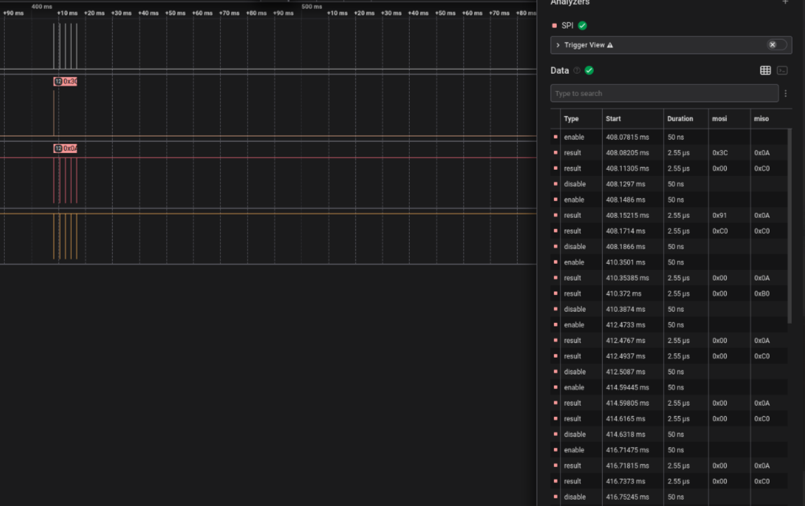
I am trying to use ADS7952 for getting multiple channels output. I am unable to slect particular channels #2, #4, #5,#6, #8, #9, #10. I am asking in the configuration point of view. The other channels #0, #1, #3, #7, #11 works fine. I am using Manula mode. I can see that the config word to select the mode and channel looks good. I didn't set any GPIO settings.

  • Hi Chandra,

    Can you share the sequence that you are sending to the device?

    Can you also share the configuration word you send to the channels that work against the channels that don't work?

    Regards,
    Joel

  • I have configured gpio using this method using this word when power up:

    uint16_t gpioSettings = 0x4001; // to set gpio mode(D15- D12)
    ADC_7952_CS_ENABLE();
    /*!< Loop while DR register in not emplty */
    while (SPI_I2S_GetFlagStatus(ADC_7952_SPI, SPI_I2S_FLAG_TXE) == RESET);
    /*!< Send word through the SPI peripheral */
    SPI_I2S_SendData(ADC_7952_SPI, gpioSettings);

    /*!< Wait for received data */
    while (SPI_I2S_GetFlagStatus(ADC_7952_SPI, SPI_I2S_FLAG_RXNE) == RESET);
    SPI_I2S_ReceiveData(ADC_7952_SPI);
    /*!< Deselect the ADC */
    ADC_7952_CS_DISABLE();

    I wrote and read the data using this method and I just send SDI four times and read SDO 4 times to get the data. 

    uint16_t outputData;
    uint16_t cmd = 0x1; // to set manual mode(D15- D12)
    uint16_t gpiomode = 0x0; // enables the programming of bit DI06-DI00
    uint16_t range = 0x00;
    uint16_t configWord = 0x0;

    //channel address is set 4 bits , D10-D07
    configWord = (cmd << 12) |(gpiomode <<11) |(channel << 7) | range;
    //debugPrintf(" SENDWORD %d\r\n", configWord);
    // Set the channel four times. and read the output data
    outputData = sendReceiveOnce(configWord);

    outputData = sendReceiveOnce(configWord);

    outputData = sendReceiveOnce(configWord);

    outputData = sendReceiveOnce(configWord);

    debugPrintf("ADC7952 channel #%d rawvalue %d\r\n", (outputData&0xF000)>>12, outputData&0x0FFF);

    I repeat the above step for each channel (0-11). I expected the channel to switch based on my selection. But it didn't happen. It changes to 0, 1, 3,7,11 only. 

  • Hi Chandra,

    Sorry for the confusion. A logic capture would be best to see the actual transactions that occur between the MCU and device. This is to isolate from any potential issues with the code. It is easier to debug the communications than the source code without any output. 

    Regards,
    Joel

  • Something like this is easiest for me to read.

    Regards,
    Joel

  • Hi Joel I am logic capture from Logic pro8. Can attach the capture file.But it was too big.

  • Hi Joel,

      Did you get my previous message? Can I provide anything else? It seems like random issue when using AutoMode 1 also.

  • Hi Chandra,

    Thanks for checking up. I haven't taken a look at it quite yet. I'll make sure to take a good look at this and get back to you within a couple hours.

    Regards,
    Joel

  • Hi Chandra,

    I composed this yesterday, but forgot to send it out. 

    I see the issue you are speaking of, but I'm not sure what would be causing this. You are sending the correct sequence to change to channel 2, yet 2 conversions later, you are seeing the device output 0x3006, indicating the conversion belongs to channel 3, so that is a little puzzling. 

    Does this occur with only one device? Are you able to try it with another device? Does the same thing occur? Are you able to zip the .sal file and attach it here? I'd like to examine if anything in the timing is off. 

    Regards,
    Joel

  • SessionManual 1.zip

    Hi Joel, Thanks for the prompt responses. I am sending the zipped file of the coresponding .sal file.

    -Chandra

  • It occurs with only the device I have. I am prototyping it. It occurs every time I use the device manual mode. Not in AutoMode 1. Is it anything to do with clock phase? Do I need to write and read at rising edge or level.

  • Hi Chandra,

    It does seem like the phase which you are changing SDI on the controller is wrong. The controller should change data on the falling edge of SCLK, so that it is stable by the rising edge of SCLK, which is when the ADS7952 clocks data in. Hopefully that makes your communications more reliable.                                   

    Regards,      
    Joel