This thread has been locked.

If you have a related question, please click the "Ask a related question" button in the top right corner. The newly created question will be automatically linked to this question.

TLA2528: Sampling Effect

Part Number: TLA2528
Other Parts Discussed in Thread: TLA2518

Tool/software:

A while ago I had been searching e2e with initial design questions.

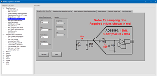
I dont know how i found it, but i ran into a spreadsheet twice where you put in the characteristics of the ADC (input resistance, sampling capacitance), and the characteristics of what is being sampled, and it tells you the effect that sampling has on the signal. 

I've searched but could not find it, do you happen to know?  (t was not for this particular adc)

thanks.

  • Hi WorkerBee,

    Could it be something from the Analog Engineer's Calculator? There are many options here, so I would recommend downloading it and taking a look to see if you find what you're looking for.

    Otherwise, it could be one of our Excel-based calculators. Do you have more information, such as what inputs the calculator takes, and what outputs it gives you?

    Regards,
    Joel

  • I was looking at one of the Excel based calculators...

    Taking a step back, I have a Thermistor that will be 23K-130K, so i'm using a 47.5K pullup.
    as its a temperature, I dont need to sample it very fast.  I do want it to be accurate.

    1) Does the TLA5218/TLA5228 discharge its sample cap? 
    Asking in a different way, if in the worst case, when i switch to a channel and take a sample with averaging of 32 samples.  is the worst case a 300ns 150ohm(typ) 15pF(typ) starting at 0V once, or 32 times?  (if S2 in your picture above is used between each sample then current draw would be much later

    i have a few choices.
    2) Buffered or non buffered
    my thought was that I do not need this to be fast, so i figured that if the loop was slow enough, it would be better to just sample the signal unbuffered to prevent extra sources of error, and minimize cost/board space.  but due to the weak signal it may be required.  the answer i think will depend on the answer to #1, but if you have any input on this choice.  it didnt seem like the ADC choices in the mentioned calculator allowed all the modifications to variables i know (input characteristics of ADC and drive strength and external filter of signal)

    3) Cfilter
    the larger this value, the more stable the signal is, and the slower it can change over time.  i think the spreadsheet i was looking at was helping to pick this.  as you connect the ADC, the signal may be affected, low large of filter do you need in order to say insert less than 0.1% error due to this.

    thanks again.

  • Hi WorkerBee,

    1. The TLA2518/2528 discharges its sampling capacitor to AVDD/2 after conversion is complete, so to answer your question, it resets 32 times, but to mid-scale, not fully down to 0V.

    It's important to keep in mind that to reach nominal resolution with an ADC, you need to allow for more acquisition time than ln(2^n)*R*C, where n is the resolution of the ADC in bits. ln(2^n) gives you the number of RC time constants you need to wait before the signal is fully settled. The result you get is in seconds.

    If you have a voltage divider, like in a thermistor circuit, the equivalent resistance is the two resistors in parallel. Then you would add any other resistors in series with the analog input. This means you can afford to sample more quickly if you have a smaller pull-up (or pull-down) resistor value, as long as the voltage drop across the thermistor is still within the input range of the ADC.

    2. In the case of thermistor circuits, it is very common to see them unbuffered. If it is a relatively static signal, it should be okay. If it is a dynamic signal, a higher frequency sine wave for example, you should consider adding an amplifier.

    3. I'll keep asking my colleagues for help in tracking down that Excel calculator. Seeing as you most likely can afford to sample slower and go without an amplifier to drive the ADC inputs, the capacitor on the ADC input contributes to the C value from number 1 above. The proper capacitor value allows you to filter higher frequency noise, while still allowing your signal to settle fully within the acquisition time.

    Regards,
    Joel