


Tool/software:
Hello,
I am trying to measure voltage in the range of 0.4 to 1.867 volts using a TI ADS114S08B ADC, the voltage is the output of an INA199C1DCK which is converting a 4-20 mA signal to voltage. I'm controlling it with an MSP430 over SPI. I am able to write to the registers on the ADS114S08B and read them back to confirm the settings are what I expect, but when I try to read the conversion data the results don't make sense. The ADC reads the same value out for multiple voltages and it’s always the same values, never slight variations (for example, it’s always 5120, not 5119 or 5121). Then the values suddenly jump to the next discrete level:

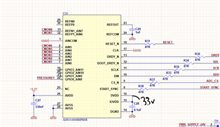
The values I read out are always exactly the same as shown above. The accuracy of the pressure transducer is around +-3 psi, but I am reading the same ADC output code for 298 and 395 psi. I measured the voltages for each level with a voltmeter to confirm. I have a unipolar power supply at 3.3V, using the internal reference of 2.5 V. I am doing a single-ended measurement, reading AIN8 as the positive voltage with AINCOM connected to GND as the negative. Here is part of my schematic:
here is a snippet of code showing how I set the registers:
unsigned int ads114s08b_configure(void){
    WREG(0b11, 0b00000000);         //  0x0   dec: 0   // Gain Setting register: disable PGA, set gain to 1
    WREG(0b100, 0b00110100);        //  0x34  dec: 52  // Data Rate register: internal clock, single-shot conversion mode, 20 SPS
    WREG(0b101, 0b00111010);        //  0x3A  dec: 58  // REF register: positive and negative reference buffers disabled, internal 2.5V reference enabled, internal reference always on
    WREG(0b10, 0b10001100);         //  select channel AIN8  dec 140
}
I have the PGA disabled and gain set to 1. My suspicion is that the issue is in the way I am reading the data. I followed the pseudo-code on page 72 of the manual to start up and configure the adc:

I was confused by the line that says "Send 16 SCLK rising edges to read out conversion data on DOUT/DRDY". In my code, I just sent a dummy byte in order to achieve that. Should I actually toggle the SCLK line 16 times or is sending a dummy byte OK?
unsigned int RDATA(void) {
    volatile unsigned int bytes = 0;
    volatile unsigned int byte1;
    volatile unsigned int byte2;

    while (!(IFG2 & UCB0TXIFG));        // Wait until the transmit buffer is empty
    UCB0TXBUF = 0b00010011;             // Send first byte

    while (!(IFG2 & UCB0TXIFG));        // Wait until the transmit buffer is empty
    UCB0TXBUF = 0b0;                    // Send first dummy byte

    while (!(IFG2 & UCB0RXIFG));        // Wait for the RX buffer to have data
    byte1 = UCB0RXBUF;                   // Return the received data
    printf("byte1: %d\n", byte1);

    while (!(IFG2 & UCB0TXIFG));        // Wait until the transmit buffer is empty
    UCB0TXBUF = 0b0;                    // Send second dummy byte

    while (!(IFG2 & UCB0RXIFG));        // Wait for the RX buffer to have data
    byte2 = UCB0RXBUF;                   // Return the received data
    printf("byte2: %d\n", byte2);

    return (byte2 << 8) | byte1;        // shift the 2nd byte recieved to the MSB and combine the bytes
    //return (byte1 << 8) | byte2;
}
When I run that code above, the first byte that comes back seems to always be 0, and the second byte is a value. I'm not sure which one is supposed to be the most significant byte and which is the least significant.
If anyone has any insights or suggestions I would greatly appreciate it. I'm happy to provide additional information.
Best,
Mason


