This thread has been locked.

If you have a related question, please click the "Ask a related question" button in the top right corner. The newly created question will be automatically linked to this question.

ADS131M06-Q1: transition response

Expert 3210 points
Part Number: ADS131M06-Q1


Tool/software:

Hi Expert,

Could you please support below questions?

(1) From Figure 8-14 in the datasheet, the time from DRDY-Hi to tSETTLE3 is a waiting time, and after that, the ADC data can be converted with Sinc3 filter data = tDATA = 1/fDATA. Since this AFE has 6 ADC channels and simultaneous conversion is performed, please first confirm whether one Sinc3 filter data can obtain AD conversion data for all 6 channels, or whether six Sinc3 filter data for 6 channels are required. Table 8-8 states that AD conversion can be performed in 0.25 msec after waiting 0.823 msec, but this 0.250 msec AD conversion is a waiting time. Please let me know if it is okay to think that AD conversion can be performed in the same time of 0.25 msec many times after the 0.823 sec waiting time.

(2) Please also let us know the time of tGC_FIRST CONVERSION, tGC_CONVERSION, and tDATA below.

Please answer with OSR=1024, 512, and 256.

The conversion period of the first conversion after the ADC channels are reset is considerably longer than the conversion period of all subsequent conversions mentioned in Equation 8, because the device must first perform two fully settled internal conversions with the input polarity swapped. The conversion period for the first conversion in global-chop mode follows Equation 9.

tGC_CONVERSION = tGC_DLY + 3 × OSR x tMOD (8)

tGC_FIRST_CONVERSION = tGC_DLY + 3 × OSR x tMOD + tGC_DLY + 3 × OSR x tMOD + 44 x tMOD (9)

(3)The time of the SPI transmission data is calculated as follows, but please confirm that it is correct before answering. If it is different, please indicate the formula and the time.

fMOD=8.192MHz/2=4.096MHz

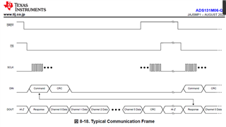
Response=16bit, Data for Channel 0-5=24bit, CRC=16bit

Total bits when sending all data from Channel 1-6 via SPI=16+24×6+16=176bit

Transmission time=176×(1/4.096*10^6)*10^-6=42.96875usec


Best Regards,

Yuki

  • Hi Yuki,

    Can you please put the customer's name into the field of Notes above the thread title?

    BR,

    Dale

  • Hello Dale,

    I put the custoer company name in the above Notes.

    BR,

    Yuki

  • Hi Yuki,

    The E2E forum was down today, I will check the details and get back to you soon. Thanks.

    BR,

    Dale

  • Hi Yuki,

    (1) ADS131M06-Q1 is a simultaneous-sampling delta-sigma ADC, every channel has its own digital filter if you look at the block diagram on the first page in the datasheet. Yes, after the fast start-up completes, the device provides conversion data from the sinc3 filter path for the third and following samples.

    (2) I do not understand the questions, you can get the value with the OSR and equation. The GC_DLY[3:0] bits in the GLOBAL_CHOP_CFG register configure the delay after chopping the inputs. tMOD is your master clock/2.

    (3) The fmod is correct, you can actually find it from the table 8-2. The word size should be same. When your data is 24-bit, the response and the CRC are  24-bit too.

    BR,

    Dale

  • Hi Dala,

    What the customer wants to know is the conversion time of the 6-channel ADC, and the transmission time until the 6-channel data are completed by SPI.

    These are not described in the datasheet.

    Could you please provide these conversion time and transmission time?

    Best Regards,

    Yuki

  • Hi YY,

    What the customer wants to know is the conversion time of the 6-channel ADC, and the transmission time until the 6-channel data are completed by SPI.

    As Dale mentioned, these values (conversion time and communication time) depend on the customer settings as well as the SCLK speed. Can you provide this information?

    -Bryan

  • Hi Bryan, Dala,

    I will send this topic via email.

    Best Regards,

    Yuki