This thread has been locked.

If you have a related question, please click the "Ask a related question" button in the top right corner. The newly created question will be automatically linked to this question.

ADS131M02: ADS131M02

Part Number: ADS131M02


Tool/software:

Hi, I am having problems modifying the gain setting registers on the ADS131M02. The ADC works on default settings as I have successful communication via SPI with a raspberrypi 5, but the problem arises when I try to change the gain of one or both channels to something else than 1.

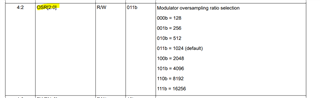
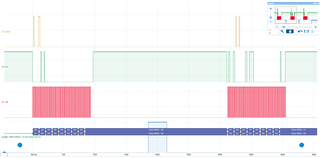
Looking at the SPI MOSI line (RPI out ADC in) on an oscilloscope the command seems correct. I built the command using the datasheet WREG command and the GAIN register on address 4, getting 32 bits:0110 0010 0000 0000 0010 0010 0000 0000 --- 011 being the WREG command, 000100 being address 4, 0000000 being 1 register to write and then the 16 bits of register settings, setting both channel gains to 2. When sending this command I receive back a correct response with the address and registers written. The ADC does not change the amplitude of the output data though (the test sin wave stays the same). 

Does anyone have any ideas what could be the problem?

  • Hi Nik Krevelj,

    Can you send us logic analyzer captures for the entire WREG command showing DIN, DOUT, SCLK, and CS?

    I assume you are using the default register settings since the issue you are having is with changing the register values.

    Also, can you clarify what you mean by:

    The ADC does not change the amplitude of the output data though

    The ADC output code should change with gain, but when you convert the code to voltage the voltage should be the same regardless of the gain (assuming the signal is still within the ADC full scale range of course)

    -Bryan

  • The ADC output code should change with gain, but when you convert the code to voltage the voltage should be the same regardless of the gain (assuming the signal is still within the ADC full scale range of course)

    This was it, I was looking at the voltage not the raw data. my mistake :)

    I do have another question about the clock register though. I again successfully write to the right address and can for example turn the channels on and off, but everytime I try to change the sampling speed it goes to 32kHz regardless of the 3 bits controlling the divider. Is there some other setting always forcing the speed to 32 or is there something else I am missing?

    ps I do have only a 8.192MHz master crystal for the chip and no outside divider.  

  • Hi Nik Krevelj,

    Glad your first issue was resolved quickly

    Can you send us logic analyzer captures for the entire WREG command showing DIN, DOUT, SCLK, and CS? The data rate should change if your are changing the values in the OSR register (see below, and confirm this is what you are doing)

    Also, how are you determining what the data rate is?

    -Bryan

  • Hi Nik Krevelj,

    One other suggestion: try entering STANDBY mode, then writing the OSR register, then issuing the WAKEUP command to see if that changes the behavior

    -Bryan

  • Two images capturing the conversation between the RPI and ADC (standby + command + active). Yellow MISO, green MOSI, red clock and blue chip select. The reply to the RWRITE command seems to have the right address (3) and number of registers written (1) but the sample rate is still always set to 32 kHz (determined by the data ready signal frequency).

    My command for the register data 0x03, 0x1F should from bit 15 to 0 enable both channels, set the divider to the max value and set the high resolution mode keeping the reserved bits in mind. 

  • Hi Nik Krevelj,

    Assuming you are using the ADC default settings, the WLENGTH = 24 bit and the default data rate is 1024, or 4kSPS. So it is not clear to me why you are seeing the DRDY pin pulsing at a frequency of 32 kHz? Can you provide a capture of multiple DRDY periods showing this behavior?

    And since WLENGTH = 24 bits, you need to send at least 4x words (96 SCLKs) to properly read out the response, ch0 data, ch1 data, and the CRC response. I only see 72 SCLKs in your transactions. Please try with the correct # of SCLKs and let me know if the situation changes

    -Bryan

  • So I should always communicate with 96 bit long SPI messages (meaning I pad out the rest of the command with zeroes)? When using this 12 byte long SPI buffer nothing really changes, the sample rate still always goes to 32kSps from the default 4 kSps. 

    Is the order of the bits in my command message for sure in the right order? The physical signal looks ok but maybe the endianess is different on the chip. For example the 0x61, 0x80, 0x03, 0x1F command sends 4 bytes: Write + address + n of register + the 16 register bits going from 15 to 0.

  • Hi Bryan, 

    I fixed my issue, the problem was not considering the 24 bit Word length. Now that I am padding the 2 command and 2 register data bytes with a zero byte to complete a 24 bit word the register is correctly written. I was sending the command and register data as a whole 4 byte chunk. 

    Thank you very much for your help!