This thread has been locked.

If you have a related question, please click the "Ask a related question" button in the top right corner. The newly created question will be automatically linked to this question.

TLA2528: sample rate

Part Number: TLA2528
Other Parts Discussed in Thread: TLA2518, ADS7138, ADS7038

Tool/software:

Hi,

We are survey for 8-CH and sample rate > 1khz, resolution = 12bit, I2C or SPI are fine. We found TLA2528 or TLA2518 seems suitable for our design.
But have some sample rate question want to check.
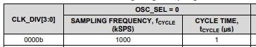
Since the 1k Hz scan is a complete set of actions, it is necessary to preliminarily evaluate the total time of the entire scanning process.
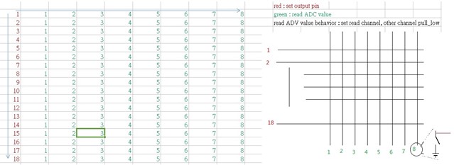
The scanning behavior is roughly as described in the figure: after setting the output pin, the input pin is read sequentially. According to the voltage division method, other input pins need to cooperate by being pulled low.
Therefore, it will be necessary to switch the PIN between GPO (General Purpose Output) and analog input modes.
The first thing to confirm is the time (t1) required between switching the PIN and reading the data.
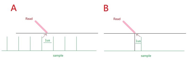
Given that the fastest sample frequency is 1 ksps (with an interval of 1 µs), it needs to be confirmed whether the sampling behavior involves continuous sampling followed by outputting the most recent sampling result when reading (Mode A), or outputting the sampling result 1 µs after the sampling command is issued (Mode B).
Thanks!
Jeff
  • Hi Jeff,

    Can you clarify whether the sampling rate is 1ksps (1ms between conversions) or 1Msps (1us between conversions). This isn't too clear to me. If 1Msps, what is the requirement to sample at that speed?

    I'm also confused on why the inputs need to change from being set as digital outputs to analog inputs, and in what sequence this needs to occur. Is it Set Pin to GPO -> Set Pin to analog input -> capture conversion data?  

    Regards,
    Joel

  • Hi Joel,

    Can you clarify whether the sampling rate is 1ksps (1ms between conversions) or 1Msps (1us between conversions). This isn't too clear to me. If 1Msps, what is the requirement to sample at that speed?

    => 

    1Msps (1µs, I mixed up the units earlier) comes from the specification
    The requirement is a scanning frequency of 1K Hz.
    Our hardware consists of a matrix with over 100 keys (e.g., 8x16). In the design, each scanning action requires reading the value of each key once to determine whether it is pressed or not.
    There is a 1ms interval between each group of scanning actions, and each scanning action requires more than 100 conversions (depending on the number of keys, with conversions performed sequentially across 8 pins)

    I'm also confused on why the inputs need to change from being set as digital outputs to analog inputs, and in what sequence this needs to occur. Is it Set Pin to GPO -> Set Pin to analog input -> capture conversion data? 

    => 

    Here’s a simple illustration: the green represents the pin for taking values, and the red represents the path to GND. When there are multiple keys, it’s necessary to determine the key pressed based on voltage division. Therefore, the pins that are not in use need to be set to ground. According to the documentation, this can be achieved by configuring the GPO and setting the output to 0.
    3. Since this is a wireless product, there are power consumption constraints. Based on the current review of the spec, does the GPI not have any interrupt functionality?
    Thanks!
    Jeff
  • Hi Jeff,

    Thanks for clarifying. The speed requirement is clearer to me. I'm still not clear on the requirement to switch between analog input and digital output though.

    Due to the power requirements, and the need for the ADC to trigger interrupts, the TLA2518 and TLA2528 don't seem to be the best options. I would turn towards the ADS7038 (SPI) or the ADS7138 (I2C), which can set the level of the GPIO pins based on events tied to the digital window comparator. I'm not sure if you can trigger an output pin to go high or low once all conversions are done though. Take a look at these devices and let me know if they fit your description better, but it doesn't seem to be practical given your requirements.

    Regards,
    Joel