


Part Number: ADC128S102
Tool/software:
Hello
I am working with an ADC128S102 and a SAMRH71 microcontroller. I have been trying to read all 8 channels in sequence with SPI.
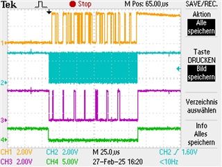
I have measured the SPI lines with an Oszilloscope to verify the way I am addressing the channels.
To me 3 signals (that are driven by the microcontroller) look exactly as I would expect them to (see figures below).
My issue now is, that the data that is returned to me on MISO does not represent the value I am measuring on the actual channel input of the ADC. For example, on channel 7 i have 0V but the adc returns a value bigger than 4000. In another case, i have varied the voltage on the input of channel 5 from 0.5V to 2V and the adc always returns a value close to 4000 as well.
I have also tried SCLK frequencies 250kHz, 1MHz, 8MHz, 10MHz, nothing seems to change.
All channels seem to return roughly the same value (between 3075 and 4025). The values that the individual channels return stay the same (+/- 1), but each channel has a little bit a different value (i.e. one always returns 3075/3075, another one always returns 4022/4023). I mention this, because at first I thought it looked like I was always getting the data of the same channel and therefore the addressing would be wrong, but this fact disproofes that theory in my opinion).
So i guess my question is, what could be a possible reason for the adc to not measure the right value or to not provide the expected data over the spi interface?
yellow: MISO
blue: SCLK
pink: MOSI
green: CS


Maybe someone has an idea what could be the issue here, I don't know what else to try or look at.
Thank you in advance!
Best regards
Tanja Regez

