This thread has been locked.

If you have a related question, please click the "Ask a related question" button in the top right corner. The newly created question will be automatically linked to this question.

ADS124S08: ADS124S08 4 RTD PT100 Review schematic

Part Number: ADS124S08

Tool/software:

Dear,

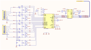
Please could you review and comment our schematics, it suppose to read 4 x PT100 RTD, all resistor on Analog part are 0,1 % except R329 (reference) is 0,01%.

We also have few questions :

1) Do we need to tie AINCOM somewhere ?

2) Does RTDx_N and RTDx_P needs to be routed with some special rules or advices to the connector ?

Thanks

Regards

  • Hi user4303883,

    Some comments about your schematic:

    • You can remove R330, C246, and C248. These are not needed since REFN0 is connected to ground
    • I assume you are going to use commands to control the ADC conversions because the START pin is tied low
    • I see you have 3x ground nets (AGND, DGND, and GND). But these are all tied together. Are you using a single, solid ground plane then? A single ground plane is what we recommend 
    • How are you going to know when new data are ready from the ADC since you are not using the DRDY pin?
    Do we need to tie AINCOM somewhere ?

    Follow the guidance in the Unused Inputs and Outputs section (10.1.5) of the datasheet

    Does RTDx_N and RTDx_P needs to be routed with some special rules or advices to the connector ?

    I am not sure what this question is asking. Can you give an example of what special rules you think might apply here so I can understand better what you are asking for?

    -Bryan

  • Hi user4303883,

    Dear Bryan

    Some comments about your schematic:

    • You can remove R330, C246, and C248. These are not needed since REFN0 is connected to ground

    OK Thanks

    • I assume you are going to use commands to control the ADC conversions because the START pin is tied low

    Yes

    • I see you have 3x ground nets (AGND, DGND, and GND). But these are all tied together. Are you using a single, solid ground plane then? A single ground plane is what we recommend 

    Always two schools about this, so from your side, I do not need to tie AGND DGND and GND in single point ? only a solid ground plane on layer 2 is that correct ?

    • How are you going to know when new data are ready from the ADC since you are not using the DRDY pin?

    This card is supposed to be used with Linux driver, and in all driver I saw there are waiting loop for conversion and not using DRDY signal, any idea why ?

    Do we need to tie AINCOM somewhere ?

    Follow the guidance in the Unused Inputs and Outputs section (10.1.5) of the datasheet

    The Chapter 10.1.5 did not speak about AINCOM
    Does RTDx_N and RTDx_P needs to be routed with some special rules or advices to the connector ?

    I am not sure what this question is asking. Can you give an example of what special rules you think might apply here so I can understand better what you are asking for?

    Length of trace or route like differential pair ?

  • Hi user4303883,

    Some feedback below:

    Always two schools about this, so from your side, I do not need to tie AGND DGND and GND in single point ? only a solid ground plane on layer 2 is that correct ?

    You can generally use a single ground plane assuming you partition the board by separating analog, digital, and power components

    This card is supposed to be used with Linux driver, and in all driver I saw there are waiting loop for conversion and not using DRDY signal, any idea why ?

    I am not sure, this driver was not developed by our group. If you want to sample continuously, you will need some way to determine when new data is ready from the ADC. If you are operating in single shot mode, where the ADC performs one conversion, and then you manually restart the conversion process, you can just use a counter/timer to know when data will be ready

    The Chapter 10.1.5 did not speak about AINCOM

    AINCOM is an analog input, so follow the guidance related to analog input

    Length of trace or route like differential pair ?

    You are measuring 2-wire RTDs, so my guess is that the sensor accuracy will dominate your overall accuracy budget. Therefore I doubt there is anything special you need to do for routing, other than following "standard" layout/routing best practices

    -Bryan