This thread has been locked.

If you have a related question, please click the "Ask a related question" button in the top right corner. The newly created question will be automatically linked to this question.

ADS1220: Only returning 0xFFFFFFFFFF after sending RDATA command

Part Number: ADS1220

Tool/software:

Hello All,

I a heating related project we are using an ADS1220.  The configuration is as following:

- 3-wire RTD

- conf0: 00h

- conf1: 00h

- conf2: 23h

-conf3: 70h

The ADC return only 0xFFFFFFFFFF after a read data command and changing the temperature on the RTD doesn't change anything.

I measure 0,983V over the 4,99KΩ Rref while over the PT100 I measure 0,011V.

Any idea what I'm doing wrong here?

Thanks for putting me on the right track.

  • Hi Denge,

    I measure 0,983V over the 4,99KΩ Rref while over the PT100 I measure 0,011V.

    These measurements do correspond to your IDAC settings and confirm you are able to configure the device.

    - conf2: 23h

    This configures the device to use the internal 2.048V reference. For your RTD application, writing '01' to the VREF field in configuration register 2 would select the external REFP0-REFN0 reference, which I'm assuming your 4,99KΩ reference resistor is connected to. 

    Can you share a schematic?

    How are you monitoring when conversion data is ready before issuing a read data command? Are you waiting the necessary time after a conversion start for your 20SPS configuration?

    In the past we have encountered an issue where with an RTD measurement and the device configured, the first conversion is wrong. This is because when the START/SYNC command is issued, the IDACs are turned on which requires time for the IDAC current path to settle for both ADC inputs and reference inputs.

    Have you tried doing more than a singular data read, to see if you get valid data readings after the first conversion once the IDAC current settles?

    Best Regards,

    Angel

  • Hello Angel,

    I changed conf2 from 23h to 63h, selecting the external REFP0-REFN0 reference.

    My schematic is a 1 to 1 copy of the schematic on page 52 of the datasheet.

    First I send the command 08h (START/SYNC), then I'm polling the DRDY until low.  Then I send the command 10h (RDATA) followed by 24 SCLK pulses.

    I do this sequence 3 times one after another but the readings stay FFFFFFFFFFh.....

    When I omit the command 10h (as in figure 63 in the datasheet) the result becomes 7FFFFFFFFFh.

    So I'm definitely overlooking something!

    Greetings

  • Hi Denge, 

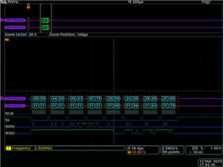
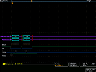
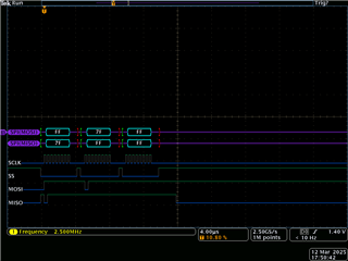
    Would it be possible to send me the logic analyzer captures of your digital communication when configuring the ADC, sending the start command, and when attempting to read data?

    Best Regards,

    Angel

  • Hi Angel,

    Herewith some traces:

    I changed to continuous mode but the result stays 7FFFFFFFFFh

    Sincerely

  • Hello Angel,

    It looks like it is getting the longer the stranger: I'm doing  3 consecutive measurements in continuous mode starting with the command 08h (START/SYNC) and then reading three times but not before the DRDY pin goes low.  The results are respectively 7B7B7Bh, FF617Bh and FF617Bh.  Heating the PT100 doesn't change the returned data although I see the voltage raising from 0,11 V to 0,14 V and the voltage over the Rref is dropping from 0,9 V to 0,5 V.

    For me it is obvious I'm doing something wrong, but what???

    Greetings,

    Hans

  • Hi Denge,

    Angel is out of the office at the moment, I can help you

    So now you are getting values other than 0xFFFFFF from the device, correct?

    Can you try restoring the ADC to its default register values (just power cycle the part), then apply a known signal to AIN0-AIN1 inputs. For example, a AA battery is ~1.5V. Then take data and see if you can get a valid measurement using a known input and nothing else (no external VREF, no IDACs, no RTD, etc.)

    Then try changing the CM bit to 1 (continuous conversion mode) and performing the same measurement as I have stated above (some known good voltage, no other register setting changes other than the CM bit)

    Let's see if you can get the basic functionality to work, then we can work on getting your RTD measurement to work

    -Bryan

  • Hello Bryan,

    It is still doing strange!  I've removed all filters and the Rref.  I connected a power supply AIN0 and AIN1 inputs.  All registers are on default.  I first send a START/SYNC command followed by RDATA and then wait for the DRDY pin to go low followed by reading from the ADS1220.  For 0,801 V the 3 consecutive readings are 18CD18h, 187318h and 181C18h.  Redoing the readings for 1,24 V results in 1FF21Fh, 203200h and 202500h.  

    When in continuous mode, I send a START/SYNC command, then wait for the DRDY pin to go low followed by 3 reading from the ADS1220.  For 0,800V on the AIN0 and AIN1 inputs the readings are 240004h, 22D300h and 24C704h. For 1,023 V the results are 30AF79h, 31F6BBh and 30C6ECh.

    The results look consistent except for the huge differences between single shot and continuous mode.

    How do I proceed now with the PT100?

    Greetings,

    Hans

  • Hi Hans,

    Removing the PT100 circuitry and applying a signal directly to be measured as Bryan suggested, These results still look quite inconsistent, the output codes vary quite a bit, and the codes don't correspond to the voltages you are applying for the ADC's default configuration. This may indicate something else is going on with your setup that causes bad data readings from your ADC. Can you share a schematic of your setup to verify all connections are okay? Is the signal applied to the analog inputs of the ADC floating, or referenced to the same GND as the ADC? Is the signal from your power supply noisy? Can you verify with a scope?

    Best Regards,

    Angel

  • Hello Angel,

    The voltage I apply to AN0 and AN1 is floating with no reference to GND.  It comes from a lab supply and is steady!  

    What is the correct values be the returned for 1V?  And what is the reason for the different results in continuous mode and single shot mode?

    I inserted the schematics I used to test.  For the PT100 I use the schematic on page 52 of the datasheet.

    Greetings,

    Hans 

  • Hi Hans,

    I can't access the link for the schematic. Can you share a picture or screenshot instead?

    For the default ADC settings (Gain of 1, internal 2.048V reference, etc.) an input voltage of 1V should correspond to an output code of around 4,096,000 in decimal (0x3E8000 in HEX). 

    Can you make your input signal be referenced to the same GND as the ADC so it is not floating? This is probably the reason the ADC output codes are inconsistent. The negative input can be tied to GND, and have the positive 1V in one of the input pins. Disable the PGA so you can make a single-ended measurement, and configure the MUX to be the input pin you are using for the 1V signal and GND (i.e. AIN0-GND). Your output code for a 1V input should be around the value I just mentioned. 

    Results shouldn't be drastically different when switching from single-shot to continuous conversion mode for the same input signal and ADC configuration. 

    First lets make sure you get the ADC operating properly and getting valid conversion data before moving on to the PT100 circuit implementation.

    Best Regards,

    Angel

  • Hello Angel,

    I grounded AIN1 —AIN0 results in negative numbers— and obtain the following results now:

    3C631Bh, 3C62CBh and 3C636Ch 

    A second run:

    3C6090h, 3C60CCh and 3C616Eh

    This a little more stable than before for now...  Now the rest!

    Greetings,

    Hans

  • Hi Hans,

    These output codes don't correspond to negative numbers, the codes converted to voltage correspond to around 0.966V, which match more closely to your 1V input signal. Section "8.5.2 Data Format" of the data sheet shows how to interpret the readings from ADC code to voltage.

    It's likely that measuring a floating voltage was the reason your measurements were moving around, but now they seem much more reasonable after establishing a common ground.

    We have the following app note that covers RTD circuits in detail: A Basic Guide to RTD Measurements (Rev. A)

    Here is an example of a circuit implementation for a 3-wire RTD application:

    Let me know if there are any questions about your implementation.

    Best Regards,

    Angel

  • Hello Angel,

    I've copied the schematic of fig. 2-3 and programmed the following configuration: conf0: 30h, conf1: D0h, conf2: 63h and conf3: 30h.

    I'm measuring 0,983 V over Rref and 0,11 V over the RTD.

    The three readings are now 0165C8h, 016473h and 0167B3h

    I hope this is an improvement (!?)

    Greeetings,

    hans

  • Hi Denge

    programmed the following configuration: conf0: 30h, conf1: D0h, conf2: 63h and conf3: 30h.

    You are enabling 50-Hz rejection while using a data rate of 2000SPS. This should only be used with a data rate setting of 20SPS so I would recommend disabling this:

    0165C8h, 016473h and 0167B3h

    These readings correspond to .0107V, .01069V, and .01079V, which are not too far off your DMM measurement of .011 for the RTD.

    Your circuit does seem to be working now.

    I would suggest increasing the IDAC current from 100uA, which would increase the voltage value of your reference, and of the RTD. You can try 250uA IDAC configuration instead. This should give you more consistent ADC output readings. If you don't need to operate at the highest data rate of 2000SPS, you can also decrease the data rate setting which should further decrease the ADC noise.

    Best Regards,

    Angel

  • Hi Angel,

    I adapted the config registers with your suggestions and it is working fine now.

    One last question: what formula did you use for the voltage to code conversion?

    Greetings,

    Hans

  • Hi Hans,

    Section "8.5.2 Data Format" of the data sheet shows how to convert between ADC code and voltage.

    The voltage value would essentially be the ADC code in decimal * voltage value of 1 LSB.

    Best Regards,

    Angel