This thread has been locked.

If you have a related question, please click the "Ask a related question" button in the top right corner. The newly created question will be automatically linked to this question.

ADS7128: How to configure the I2C address?What is the purpose of 10kΩ resistor and 160pF capacitor are placed in series with the AIN/GPIO pins?

Part Number: ADS7128
Other Parts Discussed in Thread: , ADS7830

Tool/software:

I have two questions regarding the ADS7128:

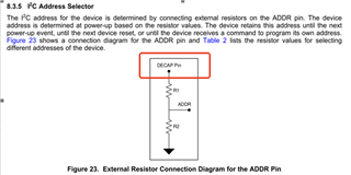
  1. On page 15 of the ADS7128 datasheet, the ADDR pin (for configuring the I2C address) is shown with a pull-up to the DECAP pin. However, in the reference design document "sbau331.pdf" (BP-ADS7128 BoosterPackTm Plug-In Module), the ADDR pull-up is connected to AVDD. Which reference should we follow for this configuration?

  2. In the reference design document "sbau331.pdf," a 10kΩ resistor and 160pF capacitor are placed in series with the AIN/GPIO pins. If we design the circuit for voltage monitoring, is the 10kΩ resistor necessary? What is its purpose?

  • Hi Hanbo,

    Thanks for reaching out. 

    1. Please follow the direction of the datasheet, and place R1 between the DECAP pin and ADDR pin.

    2. The RC filter on the EVM is a relatively aggressive value, and would be suited for mostly static signal measurement, such as voltage supply monitoring or temperature measurements. The values of the RC filter are not consistent across all applications, and it will change depending on your sampling rate target, nature of the signal measured, and any additional input impedance you might have in series with the input. The RC filter provides charge to replenish the sampling capacitor during acquisition time of the ADC, and also helps to cut off high frequency noise from the input. 

    Regards,
    Joel

  • For ADCs like your UCD90xx/ADS7830 series, we have used 0Ω resistor in parallel with a 0.1µF capacitor for voltage monitoring in many mass-production projects without issues. For voltage monitoring, which configuration is more suitable: 10kΩ + 160pF or 0Ω + 0.1µF? What are the differences between these two RC configurations in this application?

  • Hi Hanbo,

    This will depend on how fast you are sampling the channel, since the filter capacitor drops in charge during the acquisition phase to replenish the change of the sampling capacitor, and needs enough time to settle to the full accuracy of the ADC. This time is determined by the RC time constant of the device, which can be calculated, but it is easier to do a simulation.

    Can you tell me what is the sampling rate you will run the device at, and how much time between conversions for a single channel will there be?

    Regards,
    Joel

  • We are using it for DC voltage monitoring. What would be your suggestions for the sampling rate and the time interval between two conversions for a single channel? Could you also provide the corresponding values of R and C based on the suggestions?

  • Hi Hanbo,

    1ksps (1ms between conversions) is a typical sampling rate for voltage monitoring applications. To start with, 22 ohm and 0.1uF is good, as the 0.1uF capacitor will hold charge well to supply the sampling capacitor.

    Will you be dividing down the voltage you're sensing with a resistive divider before the input of the ADC? If so, what resistor values are you planning on using, and what is the input voltage?

    Regards,
    Joel

  • It is used for the voltage monitoring of 5V, with a 10KΩ pull-up resistor and a 4.7KΩ pull-down resistor.

  • Sounds great! I expect the RC values I mentioned above to work well for you in that case (22 ohm and 0.1uF).

    Regards,
    Joel