This thread has been locked.

If you have a related question, please click the "Ask a related question" button in the top right corner. The newly created question will be automatically linked to this question.

ADS1018-Q1: debugging problems when calling SPI

Part Number: ADS1018-Q1
Other Parts Discussed in Thread: ADS1018

Tool/software:

Hi team,

Ads1018 debugging encountered the following problems:
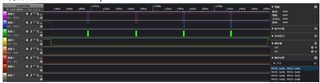
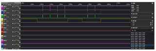
Background: spi transmission mode: single 8bits, send twice/four times
Test process: Call API: adcStartup, reply 0x058B, check the chip manual and there is no problem.
Call API: readData, request to start a conversion, but the data returned by spi indicates that the SS bit is not set, and the E768 is powered by 1.3v, but no voltage is collected.
Is there a problem with the API call?

BR,

Ethan

  • Hi Ethan,

    Can you please help us track this opportunity by entering the customer information in the Notes section of the Thread Tracking Toolkit?

    -Angel

  • Hi Angel,

    Where I can enter the Thread Tracking Toolkit?

    This is a China MM customer, but they rank top five automotive Battery packs supplier in China, the customer's information is shown as below:

    MAA: Gotion

    Website: https://www.gotion.com.cn/

    Project: BMS for Renault

    SOP: 1Q27

    BR,

    Ethan

  • Hi Ethan, 

    What do you mean by E768 is powered by E768 is powered by 1.3v? Do you have a schematic you could share?

    The SS bit always reads back as zero:

    Are you waiting enough time based on your data rate before reading a conversion results? How are you determining when conversion data is ready to be collected?

    Can you share logic analyzer captures of your digital communication?

    Best Regards,

    Angel

  • Hi Angel,

    I think the delay time is enough. Below is my logic analyzer capture information. The hardware connection is: AIN0 gives 12V voltage, AIN1 is grounded
    First I called the API: adcStartup

    Then call the API: readData to start the conversion

  • E768 powered by 1.3v was my misunderstanding at first. I mistakenly thought E768 was the AIN0 of ADS1018. You can skip this question here. Currently I give AIN0 a 12V voltage and AIN1 is grounded. Part of the schematic diagram is as follows

  • Hi Ethan,

    At the default data rate of 1600SPS you would get a new adc conversion every 625us. Are you waiting at least this long after a conversion start before collecting the adc conversion data? You can also use DRDY to determine when new conversion data is ready.

    Are you issuing a conversion start? 0x058B is simply the configuration register default value, to issue the start of a single conversion in single-shot mode, you need to write a '1' to the SS bit field (0x858B to the configuration register). 

    Are you feeding 12V directly into the AIN0 pin? The ADS1018 can only measure a max voltage up to the VDD supply. With the default configuration of the device (±2.048V FSR) you can only measure up to 2.048V. To measure a 12V signal you would have to attenuate it by dividing in down with a voltage divider resistor configuration to be within the range the ADC can measure.

    Best Regards,

    Angel