This thread has been locked.

If you have a related question, please click the "Ask a related question" button in the top right corner. The newly created question will be automatically linked to this question.

ADS7128: wide AVDD/DVDD split issue

Part Number: ADS7128
Other Parts Discussed in Thread: ADC128S102, TMP1075

Tool/software:

I have an ADS7128 set up with 5V AVDD and 1.8V DVDD. I am seeing this unexpected issue: My 1.8V rail is at 2.3V. If I remove the ADS7128, it drops down to 1.8V.

I don't see anything in the datasheet about this, am I missing it?

It is, possibly coincidentally, about 4 diode drops. My 1.8V rail (or maybe I should say my 2.3V rail) takes maybe 2mA of current.

  • Hi Andrew,

    To my knowledge, there should be no dependence of DVDD on AVDD, and there is no internal diode connection between the two (unlike the case of a device like the ADC128S102).

    Are you able to power DVDD independently from other devices connected on the 1.8V. To what voltage are your SCL and SDA pins pulled up to? If you power DVDD alone with 1.8V, with 5V on AVDD, do you see the device try to drive up the voltage of your source?

    Regards,
    Joel

  • If I remove the ADS7128, bus voltage drops to 1.8V.

    Bus voltage is provided by TLV75518PDQNR.

    I2C pullups are not present (I am debugging this board without it connected to the system first, pullups are on the system.) 

    Also on the bus: AT24CS02-MAHM-T, 4x TMP1075. That's it for 1.8V.

    Putting the same ADS7128 back on the board returns the bus voltage to ~2.3V.

    Second board also has ~2.3V (2.38) on 1.8V rail.

  • Hi Andrew, 

    Are you reading any voltage on the DVDD pin relative to ground when you have AVDD present? There's nothing within the ADS7128 that should be pulling that voltage higher than the supply.

    Can you share a schematic of your board, in case there are any paths to AVDD from DVDD external to the device? Have you tried with another ADS7128 device? 

    Regards,
    Joel

  • External paths are ruled out because removing the ADC fixes the issue. The issue exists on at least 2 boards. (One is about 2.3V, the other is about 2.4V)

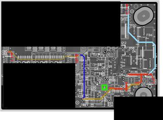
    All other devices have only 1.8V connected to them. Here's a layout (redacted) with 1.8V highlighted - it goes only to the ICs mentioned, plus some bypass caps. Note ADS7128 ground pad in green, 5V rail in bright yellow (third pin from the left on the bottom of the ADC) - not connected to 1.8V.

    No resistors from 5 to 1.8, nothing but bypass caps, TMP1075, and EEPROM on the 1.8V rail otherwise, and again, removing the ADC removes the 2.3V. Restoring the ADC restores the 2.3V

    I will try removing the 1.8V regulator just to confirm the voltage remains. I have looked at the layout at the ADC, and the 5V and 1.8V are separated.

    Schematic is proprietary etc., I can share with TI but not forums. The 1.8V is only on one page, and the only places 5V and 1.8V touch the same part are the ADC and the 5V -> 1.8V regulator.

    Regards,

    --Drew

  • Hi Drew,

    If you are able to supply an external 5V from a power supply, something to try could be to start at 5V, and slowly decrease the voltage, and check if that makes an impact on the shift you are seeing on the 1.8V rail.

    At the moment I'm a little hesitant to point to anything specifically on the ADS7128 that might be causing an issue, because the analog supply and digital supply are fully independent. DVDD is essentially a level translator to set the digital IO voltage, and AVDD is the main supply that the device actually runs on. If you find an increase to correlate with a increase in DVDD, I can check in with the design team for anything internal to the device that would potentially limit the delta between AVDD and DVDD. As of now, there isn't anything documenting that condition, and my preliminary testing hasn't shown this to be an issue either. 

    Would you be open to taking this off the forum and sharing the schematic directly via email?

    Regards,
    Joel

  • I'll see if I can get a wire on 5V to supply the voltage externally. I would be happy to share the schematic with you off the forums. Can you send an email to andrew.vanzandt@lumotive.com from your TI email?

  • Hi Andrew,

    I sent an email. Feel free to continue here or respond there.

    Regards,
    Joel

  • Update for anyone else having a similar issue: The ALERT line was connected to a differential line signal due to a DNI resistor being accidentally populated. Driving an output is not recommended.