This thread has been locked.

If you have a related question, please click the "Ask a related question" button in the top right corner. The newly created question will be automatically linked to this question.

ADS1119: ADC Selection Advice

Part Number: ADS1119
Other Parts Discussed in Thread: ADS1115

Tool/software:

Hi

I am working on a project where I need to read the voltage of two sensors. 

Sensor 1 is alphasense_pidx-a-004_datasheet_nov24_en_1.pdf

Sensor 2 is alphasense_isb_datasheet_en_1.pdf

The maximum voltage this sensor will output is 2.5V, but the region I will be measuring is most likely in the millivolt range, between 0.2V and 0.5V.

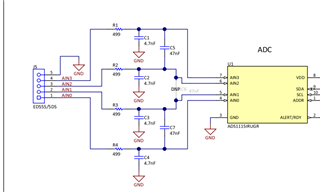
The ADC and the sensor will be placed on a daughter PCB, which will interface with I²C and 5V. If needed, I will also include a 3.3V LDO for I²C. The VCC, GND, and I²C signals will pass through a common-mode choke to minimize noise interference.

I would like to know if this device is suitable or if you would recommend a better alternative. The only requirement is that it must have an I²C interface and at least four channels. Sensor 1 provides a single signal, while Sensor 2 outputs two signals. If possible, I would like to connect the fourth channel to GND to calculate the offset—would this be recommended? Or should I follow the shorting suggestion in the datasheet?

I have a few questions:

  1. Should I use 5V as my reference? Am I correct in understanding that since the REF is differential, the top reference value will be 2.5? 
  2. Should I include additional filtering, or would it be better to use the internal 2.048V reference? I do not expect my signal to exceed 2V.
  3. I plan to take readings multiple times per minute unless it is recommended to do so every few seconds and apply averaging. How do I determine the optimal data rate setting? Since the ADC is Delta-Sigma, I believe it performs oversampling and filters outliers—am I correct?
  4. Since the device has a gain setting, would it be advisable to initially take a sample at gain 1 and, if the voltage is below 0.5V, switch to gain 4 for better resolution? Is this a recommended practice, or should I keep the gain at 1 for my application?

I appreciate your guidance on these points.

  • Hi Dharmesh,

    I would like to know if this device is suitable or if you would recommend a better alternative. The only requirement is that it must have an I²C interface and at least four channels.

    I would recommend also taking a look at the ADS1115 data sheet, product information and support | TI.com, and at the ADS112C04 data sheet, product information and support | TI.com, which is a similar device that offers a higher sample rate (2 kSPS), variable input range, iDACs, and internal temp sensor.

    The ADS1115 should be a good solution for your application. Is there a max sample rate requirement?

    Should I use 5V as my reference? Am I correct in understanding that since the REF is differential, the top reference value will be 2.5? 

    Correct, typically the max voltage that you can measure is equal to the reference voltage of the ADC.

    Should I include additional filtering, or would it be better to use the internal 2.048V reference? I do not expect my signal to exceed 2V.

    I'm not sure what you mean by this question. You can use internal reference without issues if you don't expect your signal to exceed 2V. We recommend adding an anti-aliasing filter at the analog inputs of the ADC. See example: 

    I plan to take readings multiple times per minute unless it is recommended to do so every few seconds and apply averaging. How do I determine the optimal data rate setting? Since the ADC is Delta-Sigma, I believe it performs oversampling and filters outliers—am I correct?

    If you don't have a sample rate requirement, using the lowest data rates results in the lowest noise due to the higher over sampling rate. You can learn more about the delta-sigma ADC operation from our TIPL video series: Precision labs series: Analog-to-digital converters (ADCs) | TI.com

    Since the device has a gain setting, would it be advisable to initially take a sample at gain 1 and, if the voltage is below 0.5V, switch to gain 4 for better resolution? Is this a recommended practice, or should I keep the gain at 1 for my application?

    You can change the gain settings for the different ADC sensor readings to improve dynamic range. Ultimately you have to decide what makes sense for your application and sensor measurements, gain of 1 may be good enough for your purposes.

    Best Regards,

    Angel

  • Dear

    Thank you for your reply.

    I will look into the ADS1115 in more detail, but is there a specific reason why this ADC is a better choice? Our application involves a sensor that outputs an analogue signal, and I believe the maximum voltage would be in the 0.5–1V range, so an internal reference could be sufficient.

    Regarding the sample rate, what would be recommended? The sensor output is unlikely to change very quickly, as I believe the sensor cannot react that fast. Since it is a gas sensor, I don't think the detection area would change rapidly. So, is a fast sample rate really necessary for my application?

    My other concern is noise, possibly from other electronics or RF interference. Could a fast sample rate help in detecting or mitigating noise? Additionally, if a higher sample rate is used, I presume this would mean that the I2C bus and our microcontroller should also be fast enough to handle it? Currently, I believe our I2C bus is set to operate at 100 kHz.

    I will power the ADC using an SOT-23 type LDO, with 5V as its input. I believe this should be sufficient. Regarding my question about filtering, it was originally related to using an external reference, but since I am now going to use an internal reference, this should not be required. However, the 5V supply going into my ADC PCB will pass through a common-mode choke to filter any noise, so I presume the 5V input to the LDO and the resulting 3.3V output should be clean. Additionally, I am driving the I2C signals through common-mode chokes to filter any possible noise as a good practice.

    What advantage would an anti-aliasing filter provide compared to directly inputting the sensor voltage into the ADC pins?