This thread has been locked.

If you have a related question, please click the "Ask a related question" button in the top right corner. The newly created question will be automatically linked to this question.

ADC3660: Changing DCLKIN changes measurements

Part Number: ADC3660
Other Parts Discussed in Thread: , AM5728

Tool/software:

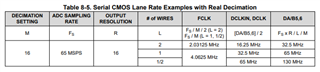
Using the same register settings, simply changing the DCLKIN frequency from 12MHz to 40.96MHz causes the data being read to change from a count of about 11000 to a count of about 12000. We are feeding a DC voltage for testing purposes.

  • Hi Tom,

    Are you in bypass mode or decimation? What is your sampling rate? Are you changing the sampling rate accordingly with the DCLKIN change?

    Thanks,

    Rob

  • Here are our register settings that work with the 12MHz input. They are written in a for loop sequentially at boot up.

    // lower 16 bits are register/value combination, e.g. register 0x7 has a value of 0x6C

        0x0000076c,
        0x00001301,
        0x00001300,
        0x00000aff,

        0x00000bee,
        0x00000cfd,
        0x00000e01,
        0x00000f02,

        0x00001810,
        0x00001902,
        0x00001b09,
        0x00001f58,
       
        0x000021f0,
        0x00002406,
        0x00002548
    Which register would need to change to accommodate the DCLKIN change?
  • Thank you Tom for the details. But also please answer my questions above.

    Regards,

    Rob

  • We are using a Real Decimation value of 16.

    Sample clock (CLKP) is the same value as the DCLKIN (working to confirm this). 

  • Hi Tom,

    Making sure I am understanding your issue correctly: you are using the ADC3660 in Real Decimation by 16 mode (you have determined that in this mode the Sample CLK and DCLK are the same frequency). You have first tested with Sample CLK and DCLK at 12MHz and get the expected number of data samples. You then change the Sample CLK and DCLK to 40.96MHz and get an unexpected number of samples?

    Afew more questions:

    1. What output resolution (14-bit, 16-bit, 18-bit) and output interface (2-wire, 1-wire, 1/2-wire) are you using?
    2. Are you using the ADC3660EVM and TI capture card? or is this your own board/FPGA design?
    3. If using the EVM with TI capture card, can you please share which capture card?
    4. When you say "data being read to change from a count of..." is this the number of samples in a certain ammount of time?
    5. How many samples are you expecting to capture at 40.96MHz?

    Best,

    Luke Allen

  • Hi Luke,

    The issue is not with the number of samples it is with the actual reading itself! When configured with 12MHz, we read a value of ~11000 counts. When configured with 40.96MHz, we read a value of ~12000 counts with the same DC input.

    1. 16-bit, 1-wire

    2. Our own board

    3. N/A

    4. No, this is the ADC counts read from the device

    5. 512 samples

  • Hi Tom,

    I see, so the ADC codes change when you are sampling a DC voltage and you change the DCLK frequency. Two things to note: as Rob mentioned, the DCLK is dependent on the Sample CLK, so you will have to change both. Also, when the ADC3660 is in 16-bit, 1-wire, Real Decimation by 16 mode, the DCLK is 0.5 * the sample CLK, they are not the same. This is likely causing the data to be read incorrectly. The DCLK Frequency can be calculated using the following equation from the datasheet (for bypass or real decimation only): 

    DCLK Freq = (Sample CLK Freq * Resolution / # Wires / Decimation Factor) / 2

    Best,

    Luke Allen

  • Luke,

    Can you please explain then, why when both DCLKIN and CLKP are set to 12MHz we are getting good data?

  • Tom,

    Just adding my $0.02 here - this could possibly be a timing issue if data looks ok at lower rate but not at faster rate. Wanted to throw it out there incase the fpga firmware design was timed/validated for 10M.

  • Hi Chase,

    Thanks for the input. We are interfacing to a AM5728 McASP port which should be rated up to 48MHz

  • Sorry, I can't say I'm familiar with our processor team's devices. Could you try a test at various sample rate's inbetween? like 15MSPS, 25MSPS, 30MSPS, etc and see where exactly it breaks? 

  • Hello Luke,

    I have not received an answer to my question about why we get good data given the above settings and both DCLKIN and CLKP are set to the same frequency of 12MHz.

    We will be working on changing the various clock rates this week to see their outcome.

  • Hi Tom,

    I assume you are not decimating, you are in bypass mode?

    Most likely 12MSPS sampling works, is that your Frame clock and data clock at exact multiples of each other, factor of 8 and so is the data.

    Decimation Mode Decimation Factor FCLK DCLK DA/DB
    Bypass 1 12M 96M 96M

    Can you try the experiment Chase suggested and change the sampling rate to 15 or 25MSPS? Does it still work correctly?

    Regards,

    Rob

  • Hi Tom,

    I cannot comment on why the data seems to be correct when the incorrect DCLK frequency is provided. I would recommend using the device as it is documented in the datasheet if you would like it to perform as documented in the datasheet. The equation to calculate the necessary DCLK frequency in Bypass / Real Deciamtion mode can be found in table 8-5 in the datasheet.

    Since you are using 16-bit, 1 Wire, real decimation by 16 mode at Fs = 40.96 MHz, your DCLk frequency should be as follows:

    DCLK Freq = (40.96M * 16 / 1 / 16) / 2

    DCLK Freq = 20.48 MHz

    Please ensure this is correct. I also tested the ADC3660 in the lab and got it running in your mode. I have attached the correct configuration for your mode. Please keep in mind that this configuration is sequence dependent, so the registers must be programmed in the same sequence for the device to be configured properly.

    0x7	0x6c
    0x8	0x0
    0x9	0x0
    0xd	0x0
    0xe	0x0
    0x11	0x0
    0x13	0x0
    0x14	0x0
    0x15	0x0
    0x16	0x0
    0x19	0x2
    0x1a	0x0
    0x1b	0x88
    0x1e	0x0
    0x20	0x0
    0x21	0xf0
    0x22	0xf
    0x24	0x7
    0x25	0x48
    0x26	0x0
    0x27	0x0
    0x2a	0x0
    0x2b	0x0
    0x2c	0x0
    0x2d	0x0
    0x2e	0x0
    0x31	0x0
    0x32	0x0
    0x33	0x0
    0x34	0x0
    // Bit Mapping Registers 0x39 to 0x88. For future development.
    0x39	0x46
    0x3a	0x47
    0x3b	0x4c
    0x3c	0x4d
    0x3d	0x4e
    0x3e	0x4f
    0x3f	0x54
    0x40	0x55
    0x41	0x56
    0x42	0x57
    0x43	0x5c
    0x44	0x5d
    0x45	0x5e
    0x46	0x5f
    0x47	0x64
    0x48	0x65
    0x49	0x66
    0x4a	0x67
    0x4b	0x6c
    0x4c	0x6d
    0x4d	0x6
    0x4e	0x7
    0x4f	0xc
    0x50	0xd
    0x51	0xe
    0x52	0xf
    0x53	0x14
    0x54	0x15
    0x55	0x16
    0x56	0x17
    0x57	0x1c
    0x58	0x1d
    0x59	0x1e
    0x5a	0x1f
    0x5b	0x24
    0x5c	0x25
    0x5d	0x26
    0x5e	0x27
    0x5f	0x2c
    0x60	0x2d
    0x61	0x42
    0x62	0x43
    0x63	0x48
    0x64	0x49
    0x65	0x4a
    0x66	0x4b
    0x67	0x50
    0x68	0x51
    0x69	0x52
    0x6a	0x53
    0x6b	0x58
    0x6c	0x59
    0x6d	0x5a
    0x6e	0x5b
    0x6f	0x60
    0x70	0x61
    0x71	0x62
    0x72	0x63
    0x73	0x68
    0x74	0x69
    0x75	0x2
    0x76	0x3
    0x77	0x8
    0x78	0x9
    0x79	0xa
    0x7a	0xb
    0x7b	0x10
    0x7c	0x11
    0x7d	0x12
    0x7e	0x13
    0x7f	0x18
    0x80	0x19
    0x81	0x1a
    0x82	0x1b
    0x83	0x20
    0x84	0x21
    0x85	0x22
    0x86	0x23
    0x87	0x28
    0x88	0x29
    0x8f	0x0
    0x92	0x0
    

    Best,

    Luke Allen

  • Hi Luke,

    I work on Tom's team. I tried the settings you posted but it made our ADC3660 device inactive, and it no longer captures data. After further investigation, we found there were some registers that were missing from your list such as 0x18 and 0x1F. These are very important registers for our application. Thank you for your suggestion. We are looking closer at our settings of the ADC3660 in comparison to other device settings to ensure they align with our design.

  • Hello,

    You are correct that these registers are not written to in the configuration I provided above. This is because the DCLKIN Buffer is enabled by default, meaning 0x18, bit 4 and 0x1F bit 6 are set to 1 by default. In 1W, Real Decimation mode, the output data is serialized, and the DCLKIN Buffer must be enabled.

    If you have any other details about your application that is relevant to the config, let me know and I can help you get a working config. If needed, let me know and we can move this discussion to an email.

    Best,

    Luke Allen