This thread has been locked.

If you have a related question, please click the "Ask a related question" button in the top right corner. The newly created question will be automatically linked to this question.

ADS125H01: ADS125H01

Part Number: ADS125H01

Tool/software:

Hello,

I use the 24 bit ADC ADS125H01 .

Inputs pin 26(AINN) and pin 27(AINP) both on ground connected for this test .

Stable +5V, +3V3,+15V and -15V.

Stable reference of 2.5V

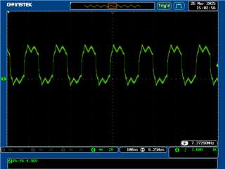
Stable 7.3728MHz oscillator and is free of overshoot and glitches

ADC settings by SPI communication

Send command 0x06 -> Reset

Write 0x0C to address 0x02

Write 0x04 to address 0x10

Write 0x0A to address 0x06

Checked the values in the addresses after writing.

Send command 0x08 -> Start conversions ( continious mode) .

Read every 75 ms 24 bits ADC result

I expect a 24 bits value around 0 volt level .

At least the last 16 bits are unstable.

Checking for floating connections on the pcb gave me no results.

First signal(Yellow)  is SPI1_SCK

Second signal(Blue) is SPI1_MOSI

Third signal(Purple) is SPI1_MISO

SPI1_CS2 is not include in the scoop view , going 'low before SPI1_SCK starts and going high after last SPI1_SCK .

SPI1_CS3 is always high .

Why is the ADC result value not stable ?


test.pdf

With regards

Paul

test.pdf

  • Hi paul brosens,

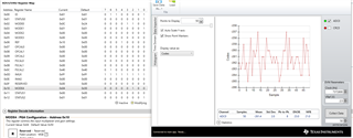
    I tried this on my EVM: setting the data rate to 5 SPS, FIR filter, internal clock, internal VREF, and grounding AIN0 and AIN1. Below is the data I got

    This matches very closely to the noise performance shown in the datasheet, so there must be an issue with your clock, your reference, or your layout. The schematic looked okay

    I would try using the internal clock and VREF, and seeing if the situation improves

  • Hello Bryan,

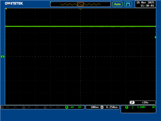
    I set the clock (7.3728MHz)and Vref (2.5V) on picture .See attachment.

    The layout is made like the example layout in the datasheet and the pcb is a 4 layers pcb.

    7.3728MHz is a short trace between oscillator and pin 18 of the ADS125H01 .

    I try the internal osc .

    With regards

    Paul

  • Hello Bryan,

    Desoldered oscillator from pcb.

    Connected pin 18 of the ADS125H01 to ground to select internal oscillator.

    Input signal of the ADS125H01 still 0Volt.

    Readout by the spi of the ADC value  still the same (least 16 bits of the 24 bits are unstable).

    With regards

    Paul

  • Hi paul brosens,

    Can you provide the actual raw hex data you are receiving from the ADC?

    If you try to measure a non-zero input, are you still getting the same odd behavior?

    -Bryan