This thread has been locked.

If you have a related question, please click the "Ask a related question" button in the top right corner. The newly created question will be automatically linked to this question.

ADS1285EVM-PDK: AVDD1 adjustment

Part Number: ADS1285EVM-PDK
Other Parts Discussed in Thread: ADS1285

Tool/software:

Hello,

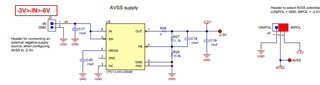
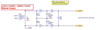
We are using the ADS1285EVM-PDK board and would like to apply bipolar signal.

An external voltage of -5V is supplying using J3, so we will have AVSS=-2.5V.

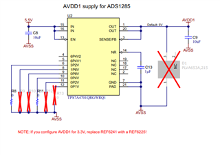
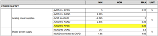
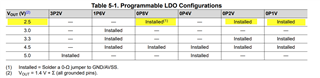
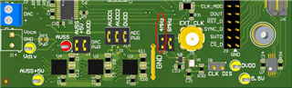
As User’s Guide page 11 describes, "Because AVDD1 is referenced to AVSS, the output AVDD1 must be modified using R8 to R13 so that the AVDD1 to AVSS voltage does not go above the recommended
operating conditions", I think I need to soler 0 Ohm resistors as shown in the Table 1 to set AVDD1=+2.5V. (Insert R10, R12, and R13, remove R8 and R11).

Am I right?

Do I need other modifications?

Best regards,

Lhagva 

  • Hello Lhagva,

    There is an error in the ADS1285EVM User's Guide.  You need to change the AVDD2 supply voltage, not AVDD1.  AVDD1 is referenced to AVSS; changing AVSS from GND (0V) to -2.5V by moving J4 to the BIPOL position and providing a negative supply to J3, will result in AVDD1 moving to +2.5V when measured with respect to AGND. 

    The total voltage on AVDD1 when measured with respect to AVSS will still be 5V , which is the correct voltage for the ADS1285 in bipolar mode.

    The AVDD2 supply is referenced to AGND, and this voltage will need to be modified from 5V to 2.5V in order to meet the required operating voltage highlighted in the datasheet.

    In order to change AVDD2 from 5V to 2.5V, you will need to Remove R14 and R17, and then install 0Ohm resistors R16 (0P8V), R18 (0P2V), and R19 (0P1V).  The resulting voltage will then be 1.4V + 0.8V + 0.2V + 0.1V = 2.5V.

    After all of these changes, you should then be able to use a DMM to measure the following voltages with respect to GND (AGND=DGND=GND):

    AVSS=-2.5V

    AVDD1=+2.5V

    AVDD2=+2.5V

    DVDD=+3.3V (provided by PHI board)

    VREFP=+1.596 (The referenced is referred to AVSS, so when AVSS=-2.5V, VREFP will be 1.596V when measured relative to GND)

    There should not be any other changes needed to the board to support bipolar supplies.  Please note that the inputs on J12 are now limited to the new bipolar supply voltages and should be no greater than +2.5V or no less than -2.5V.

    Regards,
    Keith Nicholas
    Precision ADC Applications

  • Hello Keith,

    Thank you very much for your kind support.

    We did manage capturing bipolar signals.

    But we have an issue that BUFFER_OPERATION worked and if we set to GAIN_1, GAIN_2 as below it returns constant value.

    Please tell me how to fix it.

    Best regards,

    Lhagva


  • Hello Lhagva,

    I do not see this problem on my EVM.

    You have selected 4.096MHz for the ADC clock.  In this mode, you should also set Power Mode to Low Power.

    Also, please confirm J7 is in the 4MHz position.

    Since you have reconfigured the EVM for bipolar operation, use a DMM and confirm all voltages with respect to GND are correct.

    AVSS=-2.5V

    AVDD1=+2.5V

    AVDD2=+2.5V

    DVDD=+3.3V

    Regards,
    Keith

  • Hello Keith,

    Thank you very much for your support.

    I have setup according to you guidance, all the voltages are fine and can measure with GAIN_1.

    I am sorry again, but J12 +VINP1 becomes -2.5V and the signal is shifted.

    I have checked Vdiv = 0.015V and Vocm = 0.014V. 

    Please help me where to check.

    Best regards,

    Lhagva

  • Hello Lhagva,

    With buffer mode selected, please measure J12 +VINP1 and -VINN1 with respect to ground.  Both should measure near Vocm=0.014V.

    I assume when you switch to GAIN=1 (or any other GAIN setting) then +VINP1 measures -2.5V?

    Regards,

    Keith