This thread has been locked.

If you have a related question, please click the "Ask a related question" button in the top right corner. The newly created question will be automatically linked to this question.

AFE5808A: Gain attenuation issue of the AFE5808A

Part Number: AFE5808A


Tool/software:

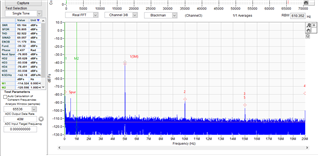
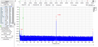
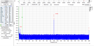
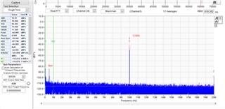
When inputting a sine wave from 5MHz to 10MHz into the input of the AFE5808a and capturing ADC data, a 6dB attenuation is observed in the 10MHz ADC data compared to the 5MHz.

I am inquiring if there might be any setting issues that could be causing this problem. The sampling frequency being used is 40MHz.

There are no HPF (High-Pass Filter) components in the circuit that would cause such attenuation.

  • Hi,

    There is LPF in the device . LPF_PROGRAMMABILITY register field will enable you to change this filter corner frequency.

    What is the purpose of this experiment ?

  • Hi, 

    while experimenting with the B-mode Bandwidth, under the 10MHz Tx condition, I observed attenuation and used a function generator on the RX path to investigate, which led to the results I initially inquired about. I suspected the LPF might be the cause, so I tried changing the cutoff frequencies to both 15MHz and 30MHz, but there was no change. Therefore, I posted the question to see if there have been any similar issues in the past.

  • I have one more question.

    Could you tell me the frequency response characteristics (Flat Gain Bandwidth) of the AFE5808A's LNA or LNA+VCA+PGA at a specific gain setting?

  • Hi,

    Do you see this amplitude difference when you probed at the input of the AFE ? Are you operating  with active termination  or without it?

  • Since the signal was not visible during the measurement, we are rechecking the signal amplitude at the AFE input.

    There was no difference observed with or without active termination.

    We would appreciate it if you could first share the requested frequency response so that we can review for any circuit or control errors.

  • Hi,

    Exp setup: 

    Clock - 40MHz

    LNA -18, PGA - 24 , DTGC enabled - -30dB

    Input signal given from signal source - 40dBm 

    Please find the attached waveform :

    1) Input - 5MHz - LPF of 15 MHz

    Fund measured : -39.1 dBFs

    2) Input - 5MHz - LPF of 30 MHz

    Fund measured : -38.6 dBFs

    3) Input - 10MHz - LPF of 15 MHz

    Fund measured : -41.1 dBFs

    4)Input - 10MHz - LPF of 30 MHz 

    Fund measured : -38.9 dBFs

    5) Input - 10Mhz LPF of 10MHz

    Fund measured : --44.1 dBFs

    Conclusion : AT 30MHz LPF corner I dont see gain difference between 5MHz to 10MHz signal.

    If your LPF is at 10 MHz then between 5MHz to 10 MHz signal - gain in varying by~5dB.

  • Thank you. I will compare it with the experimental results and let you know later whether the issue has been resolved.